


Installation
MultiView™ II T4 Installation and User Guide
11
4.3.6
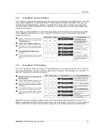
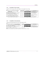
Config Mode-2: Video Coupling
Select AC or DC coupling, and DC-restore functions, to be applied to the input video.
(starting in normal-mode) Press and release the CFG
button twice to access configuration-mode-2. CFG
indicator = flashing.
Press and release the SEL button once. You will now be
able to change video-coupling settings.
LED indicators 1-2 should be illuminated (either DIM or
ON); all others (indicators 3-8) should be off.
Press the CFG button repeatedly to step through the
available video-option settings as shown below.
To leave configuration-mode step through all the options
OR leave the buttons untouched for 10 seconds.
4.3.7
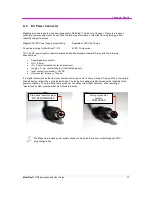
Config Mode-2: Video Termination
Select input video termination to be 75 ohms or high-impedance (Hi-Z).
(starting in normal-mode) Press and release the CFG button twice
to access configuration-mode-2. CFG indicator = flashing.
Press and release the SEL button twice. You will now be able to
change video-termination settings.
LED indicator 3 should be illuminated (either DIM or ON); all
others (indicators 1, 2, 4-8) should be off.
Press the CFG button repeatedly to toggle video termination on/off, as shown below.
To leave configuration-mode step through all the options OR leave the buttons untouched for 10 seconds.
LED1
LED2
Front Panel View
Video Options Mode
dim
dim
Auto-detect AC/DC coupling mode
based on input signal.
This is the factory-default mode.
dim
ON
Video-input is DC coupled.
ON
dim
Video-input is AC coupled, no DC-
restore function.
ON
ON
Video-input is AC coupled, DC-
restore function enabled.
LED3
Front Panel View
Video Options Mode
dim
Video input impedance is Hi-Z.
ON
Video-input impedance is 75-ohms.
This is the factory-default setting.


