background image


Specifications 

MultiView™ II T4 Installation and User Guide 

3.3 

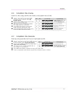
Auxiliary Signal Support 

 
The MVII-T4 design supports three types of auxiliary signals. Two are available pre-configured from the factory. 
The third option is easily user-selectable from the front-panel buttons. Note that only one type of signal is 
supported at a time: 


Factory option, MVII-T4-A: 

o


Supports L+R summed audio. 


Factory option, MVII-T4-S: 

o


Provides simplex (TX-only) serial data, even with daisy-chained receivers. 

o


Data is transmitted to all attached receivers. No data can ever be received. 

o


Receivers are not individually addressable. 

o


RS-232 interface supports a 2-wire interface: TX/GND. 

o


Baud rates up to 115.2K are supported. No settings required. 

o


Transparent to format and protocol. 


User-selectable, MVII-T4-S/PDIF: 

o


Supports digital S/PDIF audio. 

 
Note that for each T4 configuration above, the accompanying receiver device (MV500, AK600, AK1200, XR2000, 
etc.) must be similarly configured. 
 
For more specific information on MultiView™ receivers, please refer to the user-guide provided with your desired 
receiver. 

3.4 

CAT5 Cable Compatibility 

 
The MultiView™ family of products enable the highest quality video extension over common Category 5 (CAT5) 
cable. In some applications, system design or environmental factors can require the use of CAT5e and CAT6 
cabling (with and without optional shielding). Each installation may have special requirements, and it is up to the 
system designer to determine the most appropriate type of cable to deploy with MultiView™ products. In any 
case, if there is any doubt with regards to a specific type of cable it is strongly advised that actual testing be 
performed using an appropriate length of the desired cable – BEFORE that cable is specified and installed. 
 
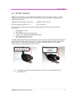
The T4 transmitter provides 4 UTP output ports. Each port in turn supports a daisy-chain CAT5 connection to 
multiple receivers. This allows one video source to be sent to many displays at the same time – with the absolute 
minimum amount of signal degradation possible. 
 
Magenta Research products are compatible with standard CAT5/5e/6 data cabling as well as specialized “low 
skew” cabling manufactured primarily for video applications. Note that some “low skew” cabling is specific to a 
particular equipment vendor or application and may not compatible with MultiView™ products. Please ensure 
any “low-skew” CAT5 cable is non-proprietary prior to purchase/installation. 
 
Standard CAT6 cable, due to the manufacture method, can exhibit much greater skew than standard CAT5/5e 
and may require skew compensation beyond what the standard product offers. Please contact Magenta 
Research for assistance. 
 
The CAT5/5e/6 cable should be suitably rated Listed cable (DUZX) communication cables, TYPE CMP, CMR, 
CMG or CM as designated in the NEC.  Cables are to be installed in accordance with the NEC and local building 
and electrical codes.  This is the responsibility of the end user/installer of this product. 

Summary of Contents for MultiView II T4

Page 1: ...Document 5310188 02 Rev 01 3 22 2012 MultiView II T4 Transmitter Installation and User Guide TM...

Page 2: ...ware or documentation including their quality performance merchantability or fitness for a particular purpose As a result this software or documentation is licensed as is and you the licensee are assu...

Page 3: ...sure which may present a risk of electric shock damage to equipment or facilities Caution Read instructions Read and understand all operating installation and safety instructions before using this equ...

Page 4: ...at Centre Chai Wan Hong Kong Main 852 3105 1493 Fax 852 3105 1491 Contact awaung magentaresearch asia com Sales awaung magentaresearch asia com Pan European Office Magenta Research LTD Main 44 7708 85...

Page 5: ...nstallation 6 4 1 Prerequisites 6 4 2 Installation Procedure 7 4 3 Configuration 9 4 3 1 DDC Mode Selection 9 4 3 2 General Configuration Settings 9 4 3 3 Setting Factory Defaults 9 4 3 4 Config Mode...

Page 6: ...panel user interface The T4 transmitter is available in two factory configured versions MVII T4 A o Supports L R summed audio MVII T4 S o Supports simplex serial Note that these two models are fundam...

Page 7: ...Magenta MultiView family of products 2 1 Front Panel interfaces The front panel of the T4 transmitter has the following ports controls and indicators There are two buttons COPY CFG and DDC MODE SEL a...

Page 8: ...nce Video output Standard VGA HD 15 video connection Will drive a 75 ohm impedance on the R G B signals DDC is supported Auxiliary Signals only one type at a time L R summed audio output Will drive a...

Page 9: ...specific display that would otherwise not work properly if simply using the factory default DDC EDID profile Finally the T4 supports a pass through mode where the DDC EDID profile of a locally attache...

Page 10: ...installation may have special requirements and it is up to the system designer to determine the most appropriate type of cable to deploy with MultiView products In any case if there is any doubt with...

Page 11: ...s not intended for nor does it support distribution through an Ethernet network Do not connect these devices to any sort of networking or telecommunications equipment Do not connect DC power until ins...

Page 12: ...ect up to 4 CAT5 cables to the transmitter LINK OUT ports All link out ports have the same signals it does not matter what order they are used in 4 Make your audio or serial connections via the phoeni...

Page 13: ...ect the CAT5 cable to the LINK IN connector If you are daisy chaining multiple receivers also connect the downstream CAT5 cable to the LINK OUT port on the receiver 3 Apply power to the receiver a The...

Page 14: ...C profile Press the DDC MODE button until the COPY indicator LED 8 is on To use the COPY mode a DDC profile must have already been read and stored into the T4 o To perform a DDC copy operation Ensure...

Page 15: ...elease the CFG button once to access configuration mode 1 CFG indicator on Press and release the SEL button twice You will now be able to change 4th pair option settings LED indicators 4 6 should be i...

Page 16: ...5 ohms or high impedance Hi Z starting in normal mode Press and release the CFG button twice to access configuration mode 2 CFG indicator flashing Press and release the SEL button twice You will now b...

Page 17: ...efresh rate may be set too high Reset to a lower refresh rate in your display configuration menu for example under Windows on a PC There may be a video skew delay issue See section on skew adjustments...

Page 18: ...isy changed within the rated cable length of the receiver When daisy chaining the maximum cable distance is not increased beyond the rated distance of the receiver used For example an AK600 can only d...

Page 19: ...al assignments Pin RGBHV VGA RGBS RGsB Com posite SVHS Y C YUV Composite Video Stereo Audio 1 Red Red Red C V Audio Left 2 Green Green Green C Y Y C 3 Blue Blue Blue U Audio Left 4 5 Gnd Gnd Gnd 6 Red...

Page 20: ...ary I O AUX IN AUX OUT 4 pin Phoenix connector signal assignments T4 PIN A Audio S Simplex Serial SPDIF Audio Composite Video use S PDIF configuration settings 1 SIG1 Left Channel Tx Signal Signal 2 G...

Page 21: ...3 RJ45 MultiViewTM link Wiring Standard PIN COLOR PAIR 1 White Orange Stripe 2 2 Orange Solid 2 3 White Green Stripe 3 4 Blue Solid 1 5 White Blue Stripe 1 6 Green Solid 3 7 White Brown Stripe 4 8 Bro...

Page 22: ...s Coaxial power connector OD 5 5mm ID 2 5mm accepted center pin diameter Length 11mm overall length of insertable plug end Inner contact pin socket 5VDC Outer contact sleeve Ground It is highly recomm...

Page 23: ...vice mounting screws 4 rack mounting screws 2211056 01 Rack mount filler plate For covering unused openings in rack mount plates Note When installing T4 devices in an area susceptible to elevated oper...

Page 24: ...lable from Magenta Research as an aid in system design and configuration You may download them from the Magenta website www magenta research com There is no charge for obtaining these drawings Drawing...

Page 25: ...il numerique de la classe A est conforme a la norme NMB 003 du Canada EUROPEAN UNION DECLARATION OF CONFORMITY Warning This is a Class A product In a domestic environment this product may cause radio...

Page 26: ...ver 5V DC Hang Down 8020102RC 00 Universal AC Plug Kit EU UK AU for 8020101RC 02 above Video Cables 8450265 06 PC video VGA Hi Res Cable M M 6 feet 8450338 01 PC video VGA Hi Res Cable M M 12 inch 845...

Page 27: ...Default Settings 9 Drawings 19 Front Panel 2 Installation 6 CAT5 Pinout 6 Prerequisites 6 Procedure 7 Mounting Kits 18 Pinouts 14 AUX I O Port 15 DC Power Input Port 17 HD15 Ports 14 RJ45 Ports 16 Pre...

Reviews: