background image


Note:  

If  the  maximum  boiler  output  capacity  is  required,  any  logs with  larger  diameters  are  necessary  to  be 
cut in half or, possibly, cut in quarters. 


3.


Technical Description  

The  boiler  is  designed  to  work  on  wood  combustion.  The  combustion  process  (which  is  based  on  power  generating 

gasification) is obtained by passing ambient air into the firebox (furnace) with the use of an exhaust fan. 

The boiler shell is made from steel plates as a welded assembly. It consists of a fuel feed hopper, which at its bottom part 

is  equipped  with  a  fireproof  insulation  brick  that  comprises  a  longitudinal  opening  (nozzle)  for  exhausting  the  combustion 
products. There is an afterburning space with ceramic tile blocks located beneath the said fireproof insulation brick.  In the rear 
part of the boiler there is a vertical tube plate that, in its upper part, merges into a collecting duct where there is a firing valve. 
The collecting duct’s rear part is equipped with an exhaust fan and socket for connecting the duct to the chimney. 

The  front  face  of  the  upper  part  comprises  a  refueling  door  and  the  lower  part  comprises  an  ash  door.    There  is  a  fan 

located on the back side. 

 The outside surface of the boiler body is thermally insulated with mineral wool inserted beneath sheet metal covers of the 

boiler’s outer shell.  

The upper portion of the boiler comprises a control panel. 


The boiler’s construction gives the following advantages:  


- the combustion process takes place at a high temperature using the function of power generating gasification; 
- the combustion air is supplied through an exhaust fan;  
- the combustion process is characterized with stable flame and a stable state and quality of combustion; 
- the large fuel feed hopper enables the burning of separate pieces of wood with maximum length of 500 mm (MA15 – 350mm, 
MA 80 up to 650 mm); 
- enables the burning of wood waste. 

4.


Operating Regulations 

Boiler Preparation for Operation  

Before the boiler is put into operation, it is necessary to ensure that your heating system has been filled with water (that 

has to be up to standard STN 07 7401:1992) and deaerated. Ceramic “U” needs to be completed and  has to be placed directly 
under  the  nozzle  –  (see  page  8). There  is  also  an  electrical  box  at  the  back  side  of  the  boiler,  which  has  a  terminal  board  for 
connection of the water pump(inclouded socket). The preset value is 50°C. 

In order to ensure proper and safe operation, your wood-fired boiler must be operated in accordance with the instructions 

contained in this operating and maintenance manual. The boiler must be operated by adults only.  


CAUTION 

When you fire up a new boiler for the first time, condensation and discharge of the condensate from the boiler may occur 

- this is not because of any defect in the boiler. After a longer duration of operation the condensation will disappear.  

Boiler Cleaning  

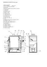
The cleaning of a boiler should be carried out as follows: Open the feeding door (2) and then sweep the ash through the 

slot (10) into the lower space. Small pieces of unburnt wood (i.e. wood coal) can be left in the charging hopper until the boiler is 
fired up next time.  Open the clean-out opening (13) and clean the tube plate by taking out of the turbulators (25) and cleaning by 
the tube cleaner. After you open the ashtray door you can rake the ash and soot out from the ashtray. 

A  cleaning  interval  depends  on  the  quality  of  fuel  you  use  (moisture  content),  the  intensity  of  heating,  the  chimney 

draught, and other specific circumstances.  The boiler should be cleaned at least once a month. The lower combustion space is 
necessary to be kept clean. You should clean it twice a week, at the least. 

Minimum once a year, we recommend to clean the wheel of the exhaust fan(4) and the air ways. We should turn off the 

control  unit  and  unplug  the  boiler  from  the  electricity.  We  can  demount  the  exhaust  fan  by  unscrewing  4  screws  under  the 
chimney  tube  (14)  and  take  out  the  exhaust  fan  with  the  sheet  metal  plate  it  is  mounted  on.  Be  careful  and  do  not  break  the 
electrical cable it is connected to the boiler. We can clean the wheel by a soft or medium brush. The we mount the fan the same 
way we have demounted it. Electrical cables should hang from the bottom of the fan. To clean the air ways, we must demount 
the front panel (26), unscrew two screws under the upper door (2) and 2 screws on the panel’s sides. Unscrew the  air flap valve 
(7) and clean the air ways. Use a plug for the holes for air ways into the nozzle, to keep it clean from the ash from the cleaning. 
After cleaning, unblock the air way into the nozzle and mount the parts in the same order from the end to the beginning. 
 

5.


Heating System and Boiler Maintenance 

You should check the water level in the heating system at least once in every 14 days. Refill water if necessary. Refilling 

must be, at all times carried out with the boiler out of operation. If, during winter season, your boiler is out of operation, there is 
a danger that the water remaining in the system may freeze causing damage to the system. In this case we can use an anti-freeze 

Summary of Contents for MA 15

Page 1: ...MA 31 MA 40 MA 49 MA 80 With an exhaust fan and CONTROL UNIT ERS AK 6000 BOILER OPERATION AND MAINTENANCE MANUAL MAGA s r o S Koll ra 86 979 01 eren any Rimavsk Sobota Slovakia Tel fax 421 47 56 34 79...

Page 2: ...and a minimum return water temperature of 60 C 140 F The pump must be connected to the thermo switch in such a way that it only operates when the required minimum temperature is reached 4 The boiler m...

Page 3: ...25 0 25 Boiler Weight kg 310 350 380 Exhaust Socket Diameter mm 159 159 159 Boiler Height mm 1120 1120 1210 Boiler Depth mm 1000 1140 1140 Boiler Width mm 570 570 570 Water capacity l 65 70 75 Boiler...

Page 4: ...red boiler must be operated in accordance with the instructions contained in this operating and maintenance manual The boiler must be operated by adults only CAUTION When you fire up a new boiler for...

Page 5: ...y For the boilers MA approximate dimensions of the boiler s cross section are 20 x 20 cm Minimum height 7 m 20 cm Minimum height 8m Exact dimensions of a chimney for this purpose in Slovakia are gover...

Page 6: ...al s such floor must be shielded with a thermally insulating fireproof board extending at least 300 mm beyond the ground plan on the firetending side and at least 100 mm beyond the ground plan on all...

Page 7: ...nce to a boiler that is currently under operation When operating a solid fuel fired boiler no inflammable liquids are permitted to be used for firing up Increasing in any manner a boiler s output capa...

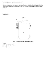
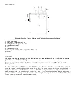
Page 8: ...et 9 Primary air inlet 10 Ceramics nozzle 11 Firing flap valve 12 Primary air inlet duct 13 Clean out cover 14 Smoke flue outlet 15 Firing valve s draw rod 16 Fuse 17 Chimney sensor flue gas temperatu...

Page 9: ...lly or through an electronic regulating device that will provide a more comfortable and more economic operation of the boiler Any related electrical wiring and devices must be done installed by author...

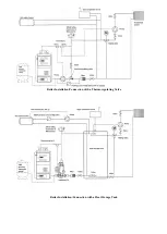
Page 10: ...Boiler Installation Connection with a Thermoregulating Valve Boiler Installation Connection with a Heat Storage Tank...

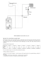
Page 11: ...he storage tank and the outdoor temperature Recommended heat storage unit sizes Boiler Type MA 15 MA 20 MA 25 MA 31 MA 40 MA 49 MA 80 Capacity kW 15 20 25 31 40 49 80 Volume l 1000 1000 1500 1500 2000...

Page 12: ...WATTS STS 20 connected to water supply piping In the event you use your own well you can protect your boiler using a backup electric power source to sustain the operation of at least one pump Another...

Page 13: ...before you fill up the boiler with heating water The Danfoss BVTS Honeywell TS 130 or the WATTS STS 20 valve the sensor of which is located in the lateral part of the boiler is intended to protect the...

Page 14: ...18 CONTROL UNIT ERS AK 6000 AK 6000 Maga Wood Gasifying Boilers Control System User Manual...

Page 15: ...outlet Do not operate the boiler unless all enclosure panels are properly in place In case of failure detection or damaging any part is important o do not touch any part of boiler o immediately discon...

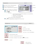
Page 16: ...l suply ending after fuel suply is passed by menu level or choice confirmation data storage o long 2 sec pressing entrance to user operation settings button decreasing adjusted value or switching depi...

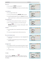
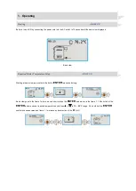
Page 17: ...peed in suction version or to 0 in blower version Combustion Continuous regulation of the fan keeps the boiler temperature on the acquired value Critical values of temperatures and thermostat automati...

Page 18: ...r and make all required action Short press the ENTER boiler gets in original state again End of the combustion Combustion temperature decreases under the minimal value boiler is automatically turned O...

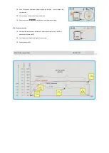
Page 19: ...two seconds long Basic view goes to the frame 1 where we use short click on the ENTER and we are in the frame 1 1 Short click of the ENTER and we can set required temperature by buttons or in 70 85 C...

Page 20: ...ut It keeps the embers waiting 50 130 C Main fan power change For example value 3 decreases fan speed in 30 3 2 2 3 Fan minimal speed This value is limit for speed decrease of the fan after reaching r...

Page 21: ...ouble click of the ESC All the connected accsesories are monitored by system Common error status is displayed by red color of the LED More exactly is error message displayed on the LCD display in the...

Page 22: ...t basic view we must hold the button ENTER two seconds long One click on the button will get us to the frame 6 By means of the ENTER button we can enter into the version display By means of the ENTER...

Page 23: ......

Page 24: ...n date Stamp and signature of the producer Date of sale Stamp and signature of the seller Date of putting into operation Stamp and signature Letter of guarantee is not valid unless properly filled in...

Page 25: ...of product Guarantee does not include any materials that are subject to common wear and tear sealing and packing rope fire concrete block and filling and sibral filling Guarantee will not be granted...

Page 26: ...Record of performed guarantee repairs Record of performed repairs within guarantee period and after Date of the record Performed activity Organization signature stamp Signature of the customer...

Page 27: ...MA 15 MA 20 MA 25 MA 31 MA 40 MA 49 MA 80 Producer MAGA s r o S KOLL RA 86 EREN ANY 979 01 RIMAVSK SOBOTA SLOVAKIA Above mentioned products are compatible with the following standards EN 303 5 2001 S...

Reviews: