Machtric S900 E Series User Manual Download Page 81

·

74

·

·

75

·

Chapter 7 Detailed Explanations of Functional Parameters

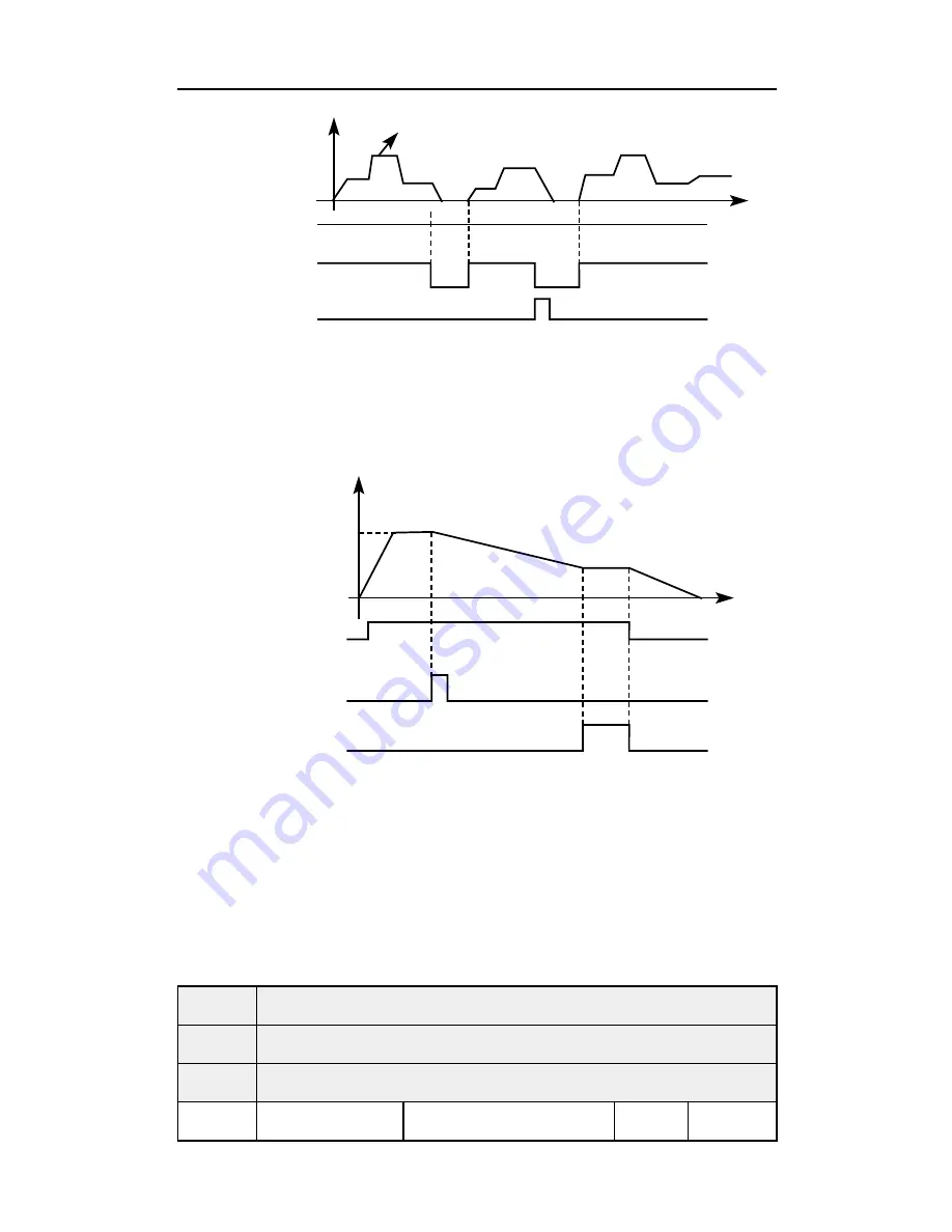
26. Winding function enable
When this signal is valid, winding function is enabled.

PLC controlled 

operation

Running signal

PLC memory cleared

Programmed operation

Time

Set frequency

Running command

Winding started

Winding completed

Time

Frequency

Introduction:

 Winding function is activated, and winding begins;

 Winding operation complete, inverter output according to the 

frequency that winding is completed. The multifunction terminal 
output the winding complete signal;

 Inverter stops, the winding complete signal reset.

P323

Output terminal M01                                      Default value 01

P324

Output terminal M02                                      Default value 02

P325

Output terminal YA, YB, YC                           Default value 03

Range

0-32

Unit

1

Summary of Contents for S900 E Series

Page 1: ...S900 E Series User manual...

Page 2: ......

Page 3: ...tention to the symbols Danger and Warning and their relevant contents Danger Assumes that incorrect handing may cause hazardous conditions resulting in death or severe injury Warning Assumes that inco...

Page 4: ...7 2 1 Unpacking Confirmation 7 2 2 Inverter model description 7 2 3 Product Specifications 8 2 4 Product seriel models 9 2 5 Product storage 9 Chapter 3 Installation of the Inverter 11 3 1 Installati...

Page 5: ...ion instruction 24 Chapter 6 Table of Function Parameters 27 Chapter 7 Detailed Explanations of Functional Parameters 42 7 1 Parameters for monitoring 42 7 2 Basic parameters 46 7 3 Parameters of basi...

Page 6: ...ck first when you have troubles 120 8 4 Inverter generated noises and their reduction techniques 122 Chapter 9 Peripheral Devices Selection 124 9 1 Peripheral Devices Description 124 9 2 Applied Braki...

Page 7: ...ce of S900 E series inverter and one copy of the instruction manual available when unpacking it Check the information on the nameplate to see if the specifications meet your order Operating voltage an...

Page 8: ...the inverter under the following enviromental conditions Otherwise the inverter may be damaged Ambient temperature 10 40 non freezing Ambient humidity 95 RH or less non condensing Ambient environment...

Page 9: ...wiring might lead to damage of the inverter The control signal lines must be kept fully away from the main circuit to protect them from noise Danger Please ensure that the power is off before junction...

Page 10: ...of the instruction manual otherwise it may cause the inverter fault or fire Please ensure that the screws of the terminals are firmly locked otherwise it may cause the inverter fault 1 4 Power on Test...

Page 11: ...h the inverter as it is hot and you may get burnt Perform setting dial and key operations with dry hands to prevent an electric shock Otherwise you may get an electric shock Please do not link or with...

Page 12: ...et damaged 1 6 Emergency stop Danger Provide a safty backup such as an emergency brake which will prevent the machine and equipment from hazardous conditions if the inverter fails When the braker on t...

Page 13: ...whether the inverter is damaged and related accessories are included If you find an omission or disagreement please contact the suppliers 2 2 Inverter model description GE Constant torque PE Variable...

Page 14: ...nput 0 01 Hz analog input 0 1 of maximum output frequency Output Frequency Accuracy 0 01Hz V F Control Setting V F curve to satisfy various load requirements Torque Control Auto increase auto raise to...

Page 15: ...omatic voltage regulation function can be selected Counter Built in 2 group of counters Protection Warning Function Overload 150 60second Constant torque Over Voltage Over voltage protection can be se...

Page 16: ...ter not to store the inverter for long time Long time storage of the inverter will lead to the deterioration of electrolytic capacity If it needs to be stored for a long time make sure to power it up...

Page 17: ...ent does not contain corrosive gas and liquid 5 The environment does not contain dust floating fiber and metal dust 6 Far away from radioactive materials and combustible substances 7 Far away from ele...

Page 18: ...ultiple inverters install them in paralled as a cooling measure If multiple inverters are installed in one control cabinet please leave enough clearances and take cooling measure Morethan 50mm Favorab...

Page 19: ...0 130 5 5 0 113 74 S900 2S0 75GE 141 5 85 0 130 5 5 0 113 74 S900 2S1 5GE 141 5 85 0 130 5 5 0 113 74 S900 2S2 2GE 151 100 139 6 5 2 111 7 88 6 S900 4T0 75GE 151 100 139 6 5 2 111 7 88 6 S900 4T1 5GE...

Page 20: ...urrent circuit breaker The input power supply has large impulse current when supplying the inverter so please pay attention to the selection of the breaker Contactor Please use electromagnetic contact...

Page 21: ...n and turn off the power of the inverter to ensure safety 4 AC current reactor a Suppress high harmonic to protect the inverter b Improve the power efficiency 5 Brake resistor When the motor is brakin...

Page 22: ...atter to enter the inverter 4 This inverter must be earthed Earthing must conform to the requirements of national and local safety regulations and electrical codes 5 Use the thickest possible earth ca...

Page 23: ...ff and check that there are no residual voltage using a tester or the like The capacitor is charged with high voltage for some time after power off and it is dangerous 12 Electromagnetic wave interfer...

Page 24: ...380V 1 5 2 5 16 12 S900 4T2 2GE 380V 2 2 2 5 16 12 S900 4T3 7GE 380V 3 7 2 5 16 12 The above data are for reference only 4 1 4 Specification of main circuit terminal The arrangement of main circuit t...

Page 25: ...GND M U V W B1 B2 Motor To connect brake resistor RA NO RB NC Voltmeter 0 10V R S T E FWD REV GND S1 S2 S3 S4 GND 4 2 2 Control terminals layout 0 4 3 7kW RA RB RC FWD REV S1 S2 S3 S4 GND FOV FIC 10V...

Page 26: ...4 35 Frequency setting 10V Frequency setting power supply Frequency setting power supply FIV FIC 36 FIV Frequency setting voltage Inputting 0 to 10VDC provides the maximun output frequency at 10V and...

Page 27: ...bles for connection to the control circuit terminals and run them away from the main and power circuits including the 200V relay sequence circuit 2 Use two or more parallel micro signal contacts or tw...

Page 28: ...operation frequency current parameter setting and irregularity content etc Status indicator various operation status Operation command key start running Programming key Stop Reset key stop running or...

Page 29: ...n to another frequency by rotating the potentiometer when the frequency is set to be controlled by the manipulator potentiometer Command for running Command for stopping applicable in the manipulator...

Page 30: ...s quick press means shift P004 STOP FWD Shift leftward for two digits and the third digit will clicker 5 Press for once P104 STOP FWD The digit is modified into 1 from 0 6 Press and hold 0001 STOP FWD...

Page 31: ...rom 5Hz 6 Press for once A00 0 RUN FWD Switch to the current display when the current output is 0A 7 Press for once Frd RUN FWD Switch to the setting interface press to switch the rotating direction 8...

Page 32: ...quency output current and running speed of the frequency converter can be monitored by switching keys during operation and the main display can be modified by P000 setting as per the practical require...

Page 33: ...functions P000 Main display data selection 0 32 1 1 42 P001 Display the set frequecy Read only 43 P002 Display the output frequency Read only 43 P003 Display the output current Read only 43 P004 Disp...

Page 34: ...44 P018 The output DC bus voltage in last alarm Read only 44 Basic functions P100 Digital frequency setting 0 00 Maximum frequency 0 01 0 00 46 P101 Frequency setting selection 0 Digital frequency se...

Page 35: ...V F maximum voltage V F intermediate voltage 500 0 0 1 400 0 53 P110 V F base frequency V F intermediate frequency max frequency 0 01 50 00 53 P111 V F intermediate voltage V F minimum voltage V F max...

Page 36: ...0Hz 0 01 0 5 59 P204 DC injection brake operation current start 0 150 rated motor current 1 100 59 P205 DC injection brake operation time start 0 25 0S 0 1 0 59 P206 DC injection brake operation curre...

Page 37: ...ions P300 FIV minimum voltage input 0 FIV maximum voltage 0 1 0 63 P301 FIV maximum voltage input FIV minimum voltage 10V 0 1 10 0 63 P30 2 FIV input filter time 0 25 0S 0 1 1 0 63 P303 FIC minimum cu...

Page 38: ...Multi speed 2 11 Multi speed 3 12 Multi speed 4 13 Accleration Deceleration terminal 1 14 Accleration Deceleration terminal 2 15 Frequency increase signal UP 16 Frequency decrease signal DOWN 17 Emerg...

Page 39: ...2 reached 12 Indication for completion of phase 13 Indication for completion of procedure 14 PID maximum 15 PID minimum 16 4 20mA disconnection 17 Overload 18 Over torque 26 Winding operation complete...

Page 40: ...ime 3 0 999 9s 0 1S 20 0 81 P404 Deceleration time 3 0 999 9s 0 1S 20 0 81 P40 5 Acceleration time 4 Jog acceleration time 0 999 9s 0 1S 2 0 81 P406 Deceleration time 4 Jog deceleration time 0 999 9s...

Page 41: ...0 1 1 0 85 P417 Allowable time of power cut 0 10s 1 5 0S 86 P418 Flank restart Current limited level 0 200 1 150 86 P419 Flank restart time 0 10s 1 50 87 P420 Fault restart times 0 5s 1 0 87 P421 Dela...

Page 42: ...32 Jump frequency 2 0 00 maximum frequency 0 01 0 90 P433 Jump frequency hysteresis loop width 0 00 2 00 0 01 0 50 90 P434 UP DOWN frequency step 0 10 00Hz 0 01 0 1 P435 UP DOWN frequency Memory optio...

Page 43: ...um frequency 0 01 40 00 93 P510 Multi speed 8 0 00 maximum frequency 0 01 45 00 93 P511 Multi speed 9 0 00 maximum frequency 0 01 50 00 93 P512 Multi speed 10 0 00 maximum frequency 0 01 10 00 93 P513...

Page 44: ...9 9s 1S 0 93 P528 PLC operation time 11 0 999 9s 1S 0 93 P529 PLC operation time 12 0 999 9s 1S 0 94 P530 PLC operation time 13 0 999 9s 1S 0 94 P531 PLC operation time 14 0 999 9s 1S 0 94 P532 PLC op...

Page 45: ...means closed 0 1s 0 1s 101 P609 PID differential time 0 00 0 20 00 S 0 means closed 0 1s 0 0 101 P610 PID action step lergth 0 00 1 00Hz 0 01 0 10Hz 101 P611 PID standby frequency 0 00 120 0Hz 0 00Hz...

Page 46: ...00 bps 2 19200 bps 3 38400 bps 0 104 P701 Communication mode 0 8N1 FOR ASC 1 8E1 FPR ASC 2 8O1 FOR ASC 3 8N1 FOR RTU 4 8E1 FOR RTU 5 8O1 FOR RTU 104 P702 Communication address 0 240 1 0 104 Advanced a...

Page 47: ...alogue output low end calibration coefficient 0 65535 1 112 P808 0 10V analog output high end calibration coefficient 0 65535 1 113 P809 0 20mA analogue output low end calibration coefficient 0 65535...

Page 48: ...ord of last faults 1 10 Displays record of last faults 2 11 Displays record of last faults 3 12 Displays record of last faults 4 13 Displays the recently set frequency of the inverter when the fault o...

Page 49: ...resent output frequency of inverter You can monitor the present output frequency of the inverter by examining parameter P002 P003 Display the output current It displays the output current of inverter...

Page 50: ...when the fault occured P016 Displays the recently output current of the inverter when the fault occured P017 Displays the recently output voltage of the inverter when the fault occured P018 Displays t...

Page 51: ...frequency setting FREE light is on which means that the keypad is displaying frequency setting 2 Press F50 0 RUN FWD Start inverter Inverter is in running and RUN light is on The image displays freque...

Page 52: ...n the inverter stops running or power is off the modified content will not be remembered instead the original P100 will be remembered When the inverter is started next time it will operate at the orig...

Page 53: ...for connection method Explanation control the output frequency through terminal FIV FC 0 10V Motor R S T U V W S900 E Power supply FIV GND E 0 10V M Motor R S T U V W S900 E Power supply 10V FIV GND...

Page 54: ...rnal UP DOWN terminals External terminals can be selected from P315 to P322 been selected one of external terminals as UP DOWN When UP is valid the frequency will go up When DOWN is valid the frequenc...

Page 55: ...running of inverter 1 I O terminal In the initial setting the forward reverse rotation signals are used as start and stop signals Turn on either of the forward and reverse rotation signals to start th...

Page 56: ...reverse rotation signal functions only as a start signal If the start signal S1 S2 is turned on and then off the start signal is held and makes a start When changing the direction of rotation turn S1...

Page 57: ...ode valid The STOP key operation of the operation panel can be made invalid to prevent unexpected stop Set 0 in P103 then press ENTER for 2s to make the STOP key operation invalid and STOP key can not...

Page 58: ...llowed Reverse of motor is enabled switching between forward and reverse is valid P105 Max frequency Initial value 50 00 Setting range Min output frequency 400 00Hz The output frequency range of inver...

Page 59: ...r Dec time can be selected via external terminal P109 V F maximum voltage Initial value 380 Setting range V F intermediate voltage 500 00 Unit 0 01 P110 V F fundamental frequency Initial value 50 Sett...

Page 60: ...ad like fan and pump Load will increase with the increase of rotation speed High start torque curve application for heavy load and load need high starting torque P109 V F maximum voltage V F maximum v...

Page 61: ...of V F curve Improper setup can cause insufficient torque or over current protection of inverter Generally do not change the setup value of this parameter while using P113 V F minimum voltage V F mini...

Page 62: ...akage current between wires and wire to ground When the environment temperature or motor load is high you shall lower the value of P115 to reduce the heating of the inverter Refer to table in P114 for...

Page 63: ...can choose from the two by setup of parameter P200 and the condition of machinery 0 Start at start frequency Most loads do not have special requirement in start Inverter output from the start frequenc...

Page 64: ...p You can choose a suitable stop mode according to the actual load 0 Deceleration to stop Once inverter receives stop command it will reduce the output frequency according to the deceleration time Run...

Page 65: ...n inverter receives stop command it reduce the output frequency until the stop frequency then it will start coasting stop or DC injection brake stop according to the setting F Set frequency Startup fr...

Page 66: ...is the period DC injection brake lasts When it is 0 DC injection brake is invalid P206 Dc braking current in stop Initial value 100 Setting range 0 150 Unit 1 P207 Dc braking time in stop Initial valu...

Page 67: ...0 Rated Motor current Initial value Setting range Unit 0 1 P211 No load current ratio of motor Initial value 40 Setting range 0 100 Unit 1 P212 Rated motor rotation speed Initial value 1420 Setting ra...

Page 68: ...lly it shall be set according to the value on nameplate To display the actual rotation speed of motor you can set parameter P212 at the actual rotation speed at 50Hz P213 Number of motor poles Set the...

Page 69: ...condition of motor 7 4 Parameters for input and output application P300 FIV minimum voltage input Initial value 0 Setting range 0 FIV maximum voltage input Unit 0 1 P301 FIV maximum voltage input Init...

Page 70: ...Initial value 1 0 Setting range 0 25 0 Unit 0 1 P303 FIC minimum current input FIC minimum current input is related to frequency of lowest analogue input Inverter will deem current signal below value...

Page 71: ...ue 0 Setting range 0 FOV maximum voltage output Unit 0 1 P307 FOV maximum voltage output Initial value 10 0 Setting range FOV minimum voltage output 10 0 Unit 0 1 The value of P306 and that of P307 de...

Page 72: ...P308 and P309 correspond to frequency of lowest analogue output and frequency of highest analogue output respectively Refer to explanations of P306 and P307 for relevant parameters P310 Frequency of l...

Page 73: ...ding to analogue minimum voltage current input P311 Direction of low analog Direction of lower analogue decides the running condition at low frequency whether it is Forward or reverse P312 Frequency o...

Page 74: ...ency 50Hz P311 1 Analogue low end direction 1 reverse P312 50 Analogue high end frequency 50Hz P313 0 Analogue high end direction 0 Forward P314 1 Analogue reverse selection 1 negative bias voltage ca...

Page 75: ...verted curve can be constituted by using P310 P314 Introduction signal input below 4mA is regarded as invalid signal by inverter P315 Multifunction input terminal FWD terminal Default value 6 P316 Mul...

Page 76: ...ion deceleration selection 2 15 Frequency increasing signal Up 16 Frequency decreasing signal Down 17 Coasting stop 18 Fault reset 19 PID function enable 20 PLC function enable 21 Timer 1 start up 22...

Page 77: ...316 4 Terminal status Running condition FWD REV ON OFF Forward ON ON Reverse OFF OFF Stop 5 Running Set terminal as running signal 6 Forward When terminal is valid motor run forward 7 Reverse When ter...

Page 78: ...d 7 P509 0 1 1 0 Multi speed 8 P510 0 1 0 1 Multi speed 9 P511 0 0 1 1 Multi speed 10 P512 1 1 1 0 Multi speed 11 P513 1 1 0 1 Multi speed 12 P514 1 0 1 1 Multi speed 13 P515 0 1 1 1 Multi speed 14 P5...

Page 79: ...t 16 Frequency decreasing signal Down signal When this terminal is valid the frequency decreases at a constant speed until operative frequency is lowest Attention Inverter will not memorize the freque...

Page 80: ...es set value corresponding multifunction output contacting action 23 Counter pulse input This terminal may accept pulse signals of no more than 250 Hz 24 Counter resetting The counted values may be re...

Page 81: ...ng started Winding completed Time Frequency Introduction Winding function is activated and winding begins Winding operation complete inverter output according to the frequency that winding is complete...

Page 82: ...load 18 Over torque 26 Winding function complete 27 Counter reached 28 Intermediate counter reached 0 Invalid Set as invalid terminal prevent false operation 1 In running Terminal is defined to be in...

Page 83: ...and Accelerating Decelerating 7 Accelerating When inverter is in the status of accelerating this contact is ON 8 Decelerating When inverter is in the status of decelerating this contact is ON 9 Under...

Page 84: ...fter three cycles of operation 13 Process completion indication In the PLC operation mode inverter output this pulse signal when inverter finished the entire program 14 PID upper limit When PID feedba...

Page 85: ...Setting 0 Output frequency 1 Output current 2 Direct voltage 3 Alternating voltage P326 output terminal FOV FOV terminal may output 0 10V voltage output may be setting in range of 0 10V through P306...

Page 86: ...D E V F 80Hz 0 5V V Parameter P105 80 00 Max frequency P106 0 00 Min output frequency P306 0 00 FOV minimum voltage output P307 5 00 FOV maximum voltage output 7 5 Secondary application group P400 Jog...

Page 87: ...ion time 1 For JOG operation the default selection is acceleration deceleration time 4 P407 Setting value of counter Default value 100 P408 Middle value of counter Default value 50 Range 0 999 9s unit...

Page 88: ...it 1 Parameter P409 is the torque limit level during constant speed When output current reaches the setting value inverter automatically reduce the output frequency in order to reduce the load When th...

Page 89: ...frequency DC voltage Voltage directrix Shutdown command P412 Automatic voltage regulation selection Default value 1 Range 0 2 Unit 1 Settings 0 Invalid 1 Valid 2 Invalid when decelerating If the input...

Page 90: ...n best voltage value may be calculated by loading condition and provided to load in order to achieve best energy saving Attention for running that load changes frequently or is almost at full load thi...

Page 91: ...valid no restart after instant power failure 1 Valid frequency tracing start up 0 Invalid Inverter clears the running command after power failure After power is recovered inverter will not start autom...

Page 92: ...failure if time of power failure exceeds set value power failure restart is invalid P418 Flank restart current limiting level Default value 150 Range 0 200 Unit 1 When inverter implements flying rest...

Page 93: ...fter fault Default value 2 Range 0 100 Unit 1 After alarm such as current over voltage and so on occurs inverter resets automatically valid when non zero as set by P420 after the period of time set by...

Page 94: ...inues operation during over torque 3 Inverter always detecting over torque inverter stop during over torque P423 Over torque detection level Default 0 Range 0 200 Minimum 1 P424 Over torque detection...

Page 95: ...ency arrive width is of a hysteresis loop which is set by P430 P430 Multifunctional output Reached frequency setting P427 No 1 timer Default value 0 Range 0 0 999 9s Unit 0 1 P428 No 2 timer Default v...

Page 96: ...2 Default value 0 Range 0 00 frequency upper limit unit 0 01 P433 Jump frequency hysteresis loop width Default value 0 50 Range 0 00 2 00 unit 0 01 If machine resonance occurred at a certain frequenc...

Page 97: ...o program Attention power cannot be cut off Stop power cut and power on inverter will not remember status before power cut off After restarting inverter will run according to initial state of program...

Page 98: ...uency PLC running mode determines running status of internal multi speed either running one circle or cycle running P502 is only valid when PLC starts up PLC pause mode means that when completing ever...

Page 99: ...ge 0 00 Max frequency Unit 0 01 P503 P517 are set of 15 speed of rated frequency in the running Regarding relationship multi speed and external terminal please refer to rated instruction 1 2 3 4 of mu...

Page 100: ...each segment Method of setting running direction The way of setting running direction by means of 16 bit binary system and then transfer to decimal system value every bit decides the corresponding ru...

Page 101: ...21 0 20 transfer to decimal system The binary system number 01010 is transferred to decimal system number 1 21 1 23 8 10 Define to P533 10 The parameter defines to P101 3 Keyboard potentiometer settin...

Page 102: ...egment 1 rated 15Hz P518 10 Segment 1 rated running duration is 10s P519 20 Segment 1 rated running duration is 20s P520 25 Segment 1 rated running duration is 25s P521 30 Segment 1 rated running dura...

Page 103: ...ation PID Control The inverter can be used to exercise process control e g flow rate air volume or pressue The terminal FIV FIC input signal or parameter setting is used as a set point and the termina...

Page 104: ...ease output frequency 1 Positive feedback mode If feedback value P603 setting value P602 inverter decrease output frequency If feedback value P603 setting value P602 inverter increase output frequency...

Page 105: ...PID figure target value setting Initial value 0 Setting range 0 0 100 Unit 0 01 Content Select FIV as feedback value 100 setting is corresponding to analog input 10V voltage PID closed loop control is...

Page 106: ...f non oscillating output After adjustment Target value Before adjustment Output Time 1 Restraint output from exceeding specific value a Decrease differential time D value b Increase integration time I...

Page 107: ...ence as the proportional band narrows the response sensitivity gain improves but the stability deteriorates e g hunting occurs P608 PID integral time Initial value 0 3s Setting range 0 0 200 0S Unit 0...

Page 108: ...ch minimum frequency in PID standby When running frequency is less than value of P610 standby duration will begin counting P612 PID standby duration When running duration of inverter is more than stan...

Page 109: ...Content 0 Not display after decimal point 1 Display 1 digit after decimal point 2 Display 2 digits after decimal point 3 Display 3 digits after decimal point 4 Display 4 digits after decimal point P6...

Page 110: ...etting range 0 5 Unit 1 Content 0 8N1 For ASCII 1 8O1 For ASCII 2 8E1 For ASCII 3 8N1 For RTU 4 8O1 For RTU 5 8E1 For RTU P701 sets the format of communication data Please see related communication sp...

Page 111: ...H 32H 33H 34H 35A 36A 37A Character 8 9 A B C D E F ASCII code 38A 39H 41H 42H 43A 44A 45H 46H 2 Character structure 10 Bit character box For ASCII Data pattern 8N1 For ASCII 10 Bit character box For...

Page 112: ...Function Hi Function code Function Lo 8 bit function code consists of 2 ASCII codes DATA n 1 Data characters n 8 bit data content consists of 2n ASCII codes DATA 0 n 16 with the maximum of 32 ASCII c...

Page 113: ...ists of 2 8 bit binary systems END Keep that zero input signal is more than or equal to 10 ms Communication Address 00H All driver Broadcasts 01H For inverter with 01st address 0FH For inverter with 1...

Page 114: ...count by byte 04H Content of data address 8102H 17H 70H Content of data address 8103H 00H 00H CRC CHK Low FEH CRC CHK High 5CH STX Address 1 0 Function 0 3 Starting address 2 1 0 2 Number of data coun...

Page 115: ...6 Data address 0 1 0 0 Data content 1 7 7 0 LRC Check 7 1 END CR LF Format of response message character string STX Address 0 1 Function 0 6 Data address 0 1 0 0 Data content 1 7 7 0 LRC Check 7 1 END...

Page 116: ...rary storage one more bit and fill 0 into high bit position Step 4 Check right shift value if being 0 store the new value for step 3 into CRC temporary storage otherwise in case of Exclusive OR A001H...

Page 117: ...storage 7 9 Advanced application parameters P800 Advanced application parameter lock Initial value 1 Setting range 0 1 Unit 1 content 0 Lock 1 Unlock If P800 is set to 0 you can not use the advanced...

Page 118: ...tage P805 Over temperature protection setting Initial value change Setting range 40 120 Unit 1 P805 sets the over temperature protection level of inverter In high temperature environment the protectio...

Page 119: ...ge 0 65535 Unit 1 P809 0 20mA analogue output low end calibration coefficient Initial value Setting range 0 65535 Unit 1 P810 0 20mA analog output high end calibration coefficient Initial value Settin...

Page 120: ...ched off a high voltage remains in the somoothing capacitor When accessing the inverter for inspection wait for at least 10 minutes after the power supply has been switched off and then make sure that...

Page 121: ...mist etc Improve environment Overall unit Check for unususal vibration and noise Check alarm location and retighten Power supply voltage Check that the main circuit voltages and control voltages are...

Page 122: ...place as required Relays as required Replacement years for when the yearly average ambient temperature is 40 Without corrosive gas flammable gas oil mist dust and dirt etc 8 3 Trouble shooting When an...

Page 123: ...V F curve 3 Check the insulation of motor and motor wire 4 Reduce the value of torque boost 5 Check input voltage 6 Check the load 7 Set tracing startup 8 Enlarge capacity of inverter 9 Sent for repa...

Page 124: ...raking unit and resistance 3 Affirm resistance setting again OU3 Over voltage during constant speed 1 Decelerate time is too short 2 Power supply voltage abnormal 3 Over load 4 Braking resistor incorr...

Page 125: ...n OL1 during acceleration OL2 during deceleration OL3 during constant speed OT0 during stop Motor overload 1 The motor for use under overload 2 Acceleration time is too short 3 Motor protection settin...

Page 126: ...er setting is wrong After stopping operation make parameter setting Err Wrong parameter group The parameter does not exist or the factory setting parameter Quit this parameter 8 3 Check first when you...

Page 127: ...ctive actions a Check that the load is not too heavy Lighten the load b Is the fan for the motor is running check for accumulated dust c Check that the P208 Torque boost setting is correct d Was the m...

Page 128: ...C filter valid to minimize interference a Decrease carrier frequency P115 b Install a noise filter on the inverter output side to reduce the electromagnetic nois generated from the inverter c Install...

Page 129: ...ables and connect the sheathes of the shield cables to terminal SC Earth the inverter motor etc at one point Techniques to reduce noises that enter and malfunction the inverter When devices that gener...

Page 130: ...nce an In rush curreH flows in the inverter at power on Magnetic coHactor MC Install the MC to ensure safety Do not use this MC to start and stop the inverter Doing so will cause the inverter life to...

Page 131: ...ake resistor Brake Torque 10 ED Motor Output kW Remark Power W Resistance value S900 2S0 4GE 80 200 125 0 4 S900 2S0 75GE 100 200 125 0 75 S900 2S1 5GE 300 100 125 1 5 S900 2S2 2GE 300 70 125 2 2 S900...

Page 132: ...king torque the Braking resistor values are differeH and the calculation formula is as follow The braking power is related to braking torque and braking frequency the foregoing illustration gives the...

Page 133: ...instruction P101 1 Analog voltage input as frequency setting external potentiometer P102 1 External terminal control P317 6 The forward rotation start signal is assigned to the terminal S1 P318 7 The...

Page 134: ...ration Instruction of S900 E Series Inverter K1 forward rotation K2 reverse rotation K3 Stop Output frequency is controlled by potentiometer K1 K2 K3 Frequency Running frequency potentiometric control...

Page 135: ......

Page 136: ...lock B Section F Binjiang Industrial park Jiangbin Road Licheng District Quanzhou Fujian China Tel 86 595 22555311 Fax 86 595 22555211 E mail jimmy machtric com Website www machtric com All rights res...

Reviews: