


6
2.
Digital (pulse and direction) interface for 6 axis motion control
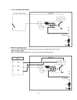
The IO6 breakout board provides differential and single ended step and direction both
of which may be employed at the same time.
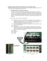
a.
Differential step and direction interface
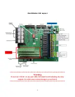
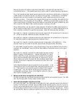
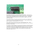
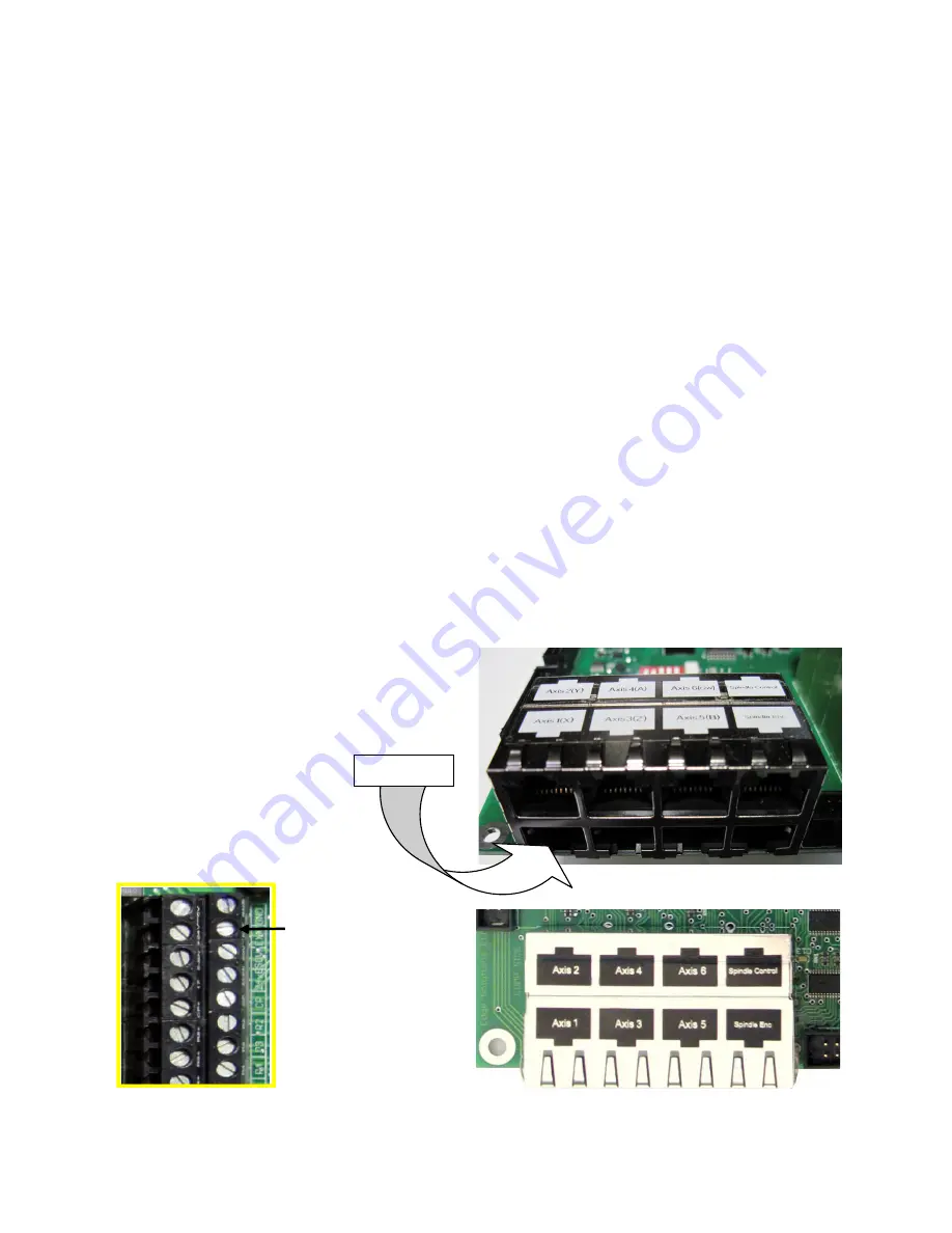
The first 6 jacks of the 8 jack module provide differential step and direction
outputs for servo drives. The differential interface provides common mode noise
rejection. This interface requires the use servo drives that expect a differential
input or differential adapters connected near the servo drives. Modular Jack
for Axis 1 is located on the bottom row of jacks, closest to Parallel Port 1. (See
Figure 5)
The pin-out for each of these six mod jacks is:
Pin 1.
Optional Input pin for limit switch input signals. This pin connects to
parallel port 1 input pins 11, 12, 13, and 15 for axis 1-4 respectively and
parallel port 2 input pins 10 and 11 for axis 5 and 6 respectively.
(Consult the Opto_Input Connection Guide 11)
Pin 2.
Drive error signal (Hard wired to opto-coupled circuit connected to input
pin 10 of the PC port).
Pin 3.
Direction
Pin 4.
Drive Enable. The drive enable voltage is determined by the voltage
that is provided by the user at the EXT (External Enable Voltage Supply)
terminal. (See Figure 4) The enable signal will be active whenever the
Charge Pump circuit is enabled.
Pin 5.
GND
Pin 6.
Direction/
Pin 7.
Step
Pin 8.
Step/
External Power for
drive enable (EX-EN)
Figure 4
Figure 5
External Power for
drive enable (EX-EN)
Axis 1 (X)
Summary of Contents for IO6 V4.0
Page 2: ...2 This page was intentionally left blank...
Page 24: ...21...


