


9
4.
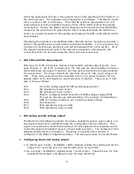
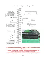
Go to Config / Ports&Pins / Spindle Setup / Relay Output. Enter “1” for M3 output
# and “1” for M4 output #.
5.
Go to Config / Motor Tuning / Spindle. On Steps per Unit enter 1000, change the
velocity to 1575. Set acceleration to 50 or choose the acceleration that you feel
comfortable with. The acceleration set here must be within the range of the VFD
acceleration setup if a VFD is used. Mach3 will then produce the appropriate
voltage for speeds less than the maximum.
7.
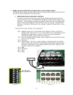
I06 Inputs for measuring spindle RPM
The IO6 provides interfaces for receiving a pulse stream from a sensor configured to a
rotating spindle, which is used to measure the RPM of the spindle. The IO6 provides
for three different methods of receiving this pulse stream. The IO6 also includes a
pulse stretching circuit which sends a 9 us pulse to the CNC control for any length input
pulse received by an encoder or photo interrupter sensor configured on the spindle.
This pulse stretching circuit ensures that the MACH3 control will not miss any pulses.
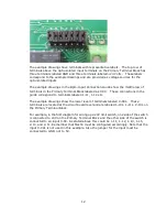
An incremental encoder, providing the usual 5 volt A, A/ B, B/, I, and I/ differential
signals can be used to sense spindle RPM. Using differential signals provides common
mode noise reduction for reliable pulse monitoring. Modular Jack #7 (located on the
lower layer of the 8 jack module) is provided for a convenient differential spindle
feedback connection to the IO6. Obviously, to utilize these noise immune inputs, a
differential encoder driver or differential encoder must be mounted on the spindle, and
connected to the cable with the CAT5 mod jack connection for mating to the IO6 board.
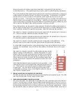
The system integrator may choose to select only the index pulse provided by an
encoder mounted on the spindle, or all of the encoder signals (A, B, and I) provided by
using the Dip Switch settings below. The use of the A and B encoder inputs may be
useful in applications where the exact rotational position of the spindle is needed.
Normally, MACH3 derives spindle speed from one incoming pulse such as the index
pulse.
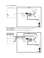
Alternatively, a photo interrupter sensor, inductive sensor or other sensor can be
configured to produce one pulse per revolution of the spindle. The signal can be
converted near the sensor to differential through the use of a converter such as the
MachMotion’s R2210 converter and then interfaced to the IO6 through a shielded CAT5
cable and Mod Jack #7 mentioned in the previous paragraph. The inputs to this mod
jack are expected to be based on 5v differential signals, as are provided by a 26C31
Differential driver. The pin out of Mod Jack #7 is provided:
Pin 1
Encoder A
Pin 2
Encoder A/
Pin 3
Encoder B
Pin 4
+5V to power the encoder
Pin 5
GND
Pin 6
Encoder B/
Pin 7
Encoder I
Pin 8
Encoder I/
Both spindle RPM monitoring signals and Spindle speed control output signals can be
connected to the IO6 board through the mod jacks as mentioned above. The speed
measuring signal can also be a single ended opto-isolated signal connected to the
Summary of Contents for IO6 V4.0
Page 2: ...2 This page was intentionally left blank...
Page 24: ...21...


