


12
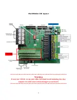
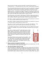
The example drawings have terminals with representative labels. The top row of
terminals above the opto-isolated input terminals on the Primary Terminal Block has
three terminals labeled GND and three terminals l24 Volts. These labels
correspond to the example drawings and are provided as voltage sources for the
opto-isolated inputs.
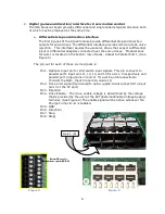
The example drawings in the Opto-Input Connection Guide show the middle row of
terminals in the Primary Terminal Block labeled as X-XX. These connections in the
guide correspond to terminals labeled 1-11, 1-12 etc.
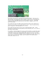
The example drawings show the lower level of terminals labeled X-XXL. These
terminals are located at the circuit board level and are labeled 1-10L, 1-11L, 2-10L on
the Primary Terminal Block.
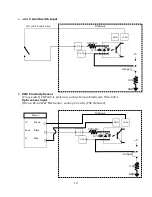
For example, in the first diagram for wiring up a 24V limit switch, one side of the switch
is connected to 24V on the Primary Terminal Block and the other side of the switch is
connected to an input X-XX. As stated above this could be 1-11, 1-12, 1-13, 1-15,
2-10, and 2-11. Remember that Mach3 must be configured accordingly. Note that the
input X-XXL is not used in this example. Also the jumper for the input must be
connected to GND, not to 5V.
Summary of Contents for IO6 V4.0
Page 2: ...2 This page was intentionally left blank...
Page 24: ...21...


