


1
Table of Contents
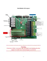
MachMotion IO6 Layout .................................................................... 3
IO6 General Description ................................................................... 4
Features .............................................................................................. 4
Input & Output List ............................................................................... 4
Use of this manual ................................................................................ 4
IO6 System Requirements ................................................................ 4
•
2 PC Parallel ports ........................................................................... 4
•
Power Requirements ........................................................................ 4
Description of the interface assemblies ............................................ 5
2.
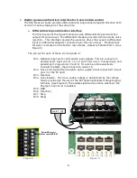
Digital (pulse and direction) interface for 6 axis motion control ........... 6
a.
Differential step and direction interface ............................................................. 6
3.
Spindle Control Overview ............................................................... 7
4.
IO6 CW and CCW relay outputs ...................................................... 8
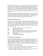
5.
I06 analog spindle voltage output ................................................... 8
6.
Configuring the 0-10V analog output ............................................... 8
7.
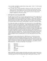
I06 Inputs for measuring spindle RPM ............................................. 9
9.
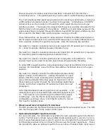
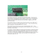
Opto-Isolated digital inputs terminals ............................................ 10
1.
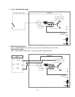
+24 V Limit Switch Input ......................................................................................................... 13
2.
PNP Proximity Sensor .............................................................................................................. 13
Opto sensor input ........................................................................................................................... 13
3.
NPN Proxy 5V only. .................................................................................................... 14
Opto sensor input ........................................................................................................................... 14
4.
+5V input signal or drive error input ....................................................................................... 14
5.
+24V signal input ..................................................................................................................... 15
6.
Digitizing Probe Input ................................................................................... 15
11.
Digitizing probe input terminal ...................................................... 16
12.
Estop terminals .......................................................................... 16
13.
Error Input ................................................................................. 16
Summary of Contents for IO6 V4.0
Page 2: ...2 This page was intentionally left blank...
Page 24: ...21...


