


7
b.
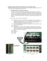
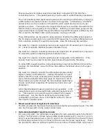
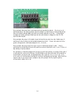
Single ended (non-differential) step and direction interface
The Primary Terminal Block has six phoenix screw terminal connectors for single
ended (5V TTL) step and direction control signal access for connection to servo
drives.
The labeling below the six green phoenix terminal block indicates the
corresponding PC parallel port pin that is interfaced by the terminal. For
example, terminals labeled D-2, D-4, D-6, D-8, D-14, and D-1 are to be
configured as direction outputs in the Mach3 configuration table, for axis 1-6
respectively. Terminals 3, 5, 7, 9, 16, and 17 are to be configured as step
outputs for axis 1-6 respectively. The Ground terminals for these signals are
also marked on the circuit board.
3.
Spindle Control Overview
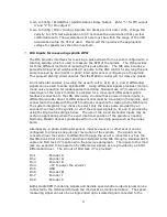
The IO6 controls the spindle in this way: The machine operator manually sets the
spindle speed on the Mach3 control panel display or it is set via the G-code file. Then
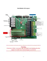
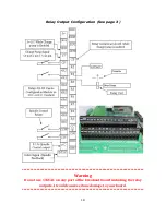
**************WARNING**************
All Servo drive fault signals should be connected together so that a
failure in one drive shuts down every servo drive at the same time.
Failure to configure the servo drives in this manner can cause DEATH,
INJURY or serious PROPERTY DAMAGE. Do not install drives that do
not share the same fault line.
**************WARNING**************
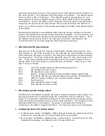
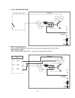
Direction Row
2, 4, 6, 8, 14
Step Row
3, 5, 7, 9, 16, 17
Ground
PC Parallel Port
#1 Pin-outs
2
4
6
8
14
1
3
5
7
9
16 17
GND GND GND GND GND GND
Step Row
Direction Row
Figure 6
Summary of Contents for IO6 V4.0
Page 2: ...2 This page was intentionally left blank...
Page 24: ...21...


