


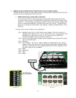


11
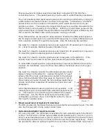
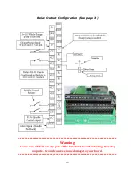
Figure 9
LED indicator below the corresponding input below the Primary terminal block. See
page 17 figure 13 and 14.
These seven inputs can be connected to a number of different types of devices and
configured as described in the next section (10) entitled, OPTO-Input Connection
Guide.
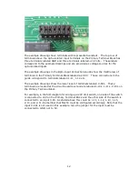
10.
Opto-input connection guide
This guide will assist the systems integrator in the installation of the seven general
purpose opto-isolated inputs. The options for the inputs are given as examples in this
guide.
The various options are selected by installing a Jumper on one of two pairs of pins for
each of the seven inputs. The Jumper will connect between a center pin and either a
pin in the row labeled GND or to a pin in the row l5V. The Jumpers correspond
to the appropriate input port/pins and are labeled A10, A11, A12, A13, A15, B10, and
B11 on the printed circuit board.
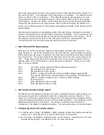
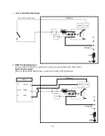
Primary
Terminal
Block
+24v
GND
+5v
P
o
rt
1
—
1
1
P
o
rt
1
—
1
3
P
o
rt
1
—
1
2
P
o
rt
1
—
1
0
(
E
rr
o
r)
P
o
rt
2
—
1
0
P
o
rt
2
—
1
1
P
o
rt
2
—
1
2
P
o
rt
1
—
1
5
P
o
rt
2
—
1
3
P
o
rt
2
—
1
5
P
o
rt
1
-1
1
L
P
o
rt
1
-1
3
L
P
o
rt
1
-1
2
L
P
o
rt
1
-1
0
L
P
o
rt
2
-1
0
L
P
o
rt
2
-1
1
L
P
o
rt
1
-1
5
L
Summary of Contents for IO6 V4.0
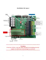
Page 2: ...2 This page was intentionally left blank...
Page 24: ...21...


