


MacDonald Steel Limited
BREWERY SYSTEMS DIVISION
8
REV 00
MACHINE SETUP
LIGHTS
Light strips are 24vdc LED’s.
FILL TUBES
The fill tubes must be installed before operating the machine. The fill tubes are designed to reach near
the bottom of the bottle when the head is lowered. If filling more than one bottle size, be sure to use the
appropriate length fill tube. Failing to use the proper size could result in excess foaming or breaking of
the fill tube.
Use the “
Manual Control
” screen to manually operate the heads. Reduce the air pressure to 5 PSI or less
so the heads operate slowly. The fill tubes are threaded on one end. Carefully screw the tube onto the
head. Align the tube by slightly bending them if necessary to be centered in the bottle opening.
If necessary short fill nozzles are available for “fill from top” filling, if the displacement of the fill tube is too
high.
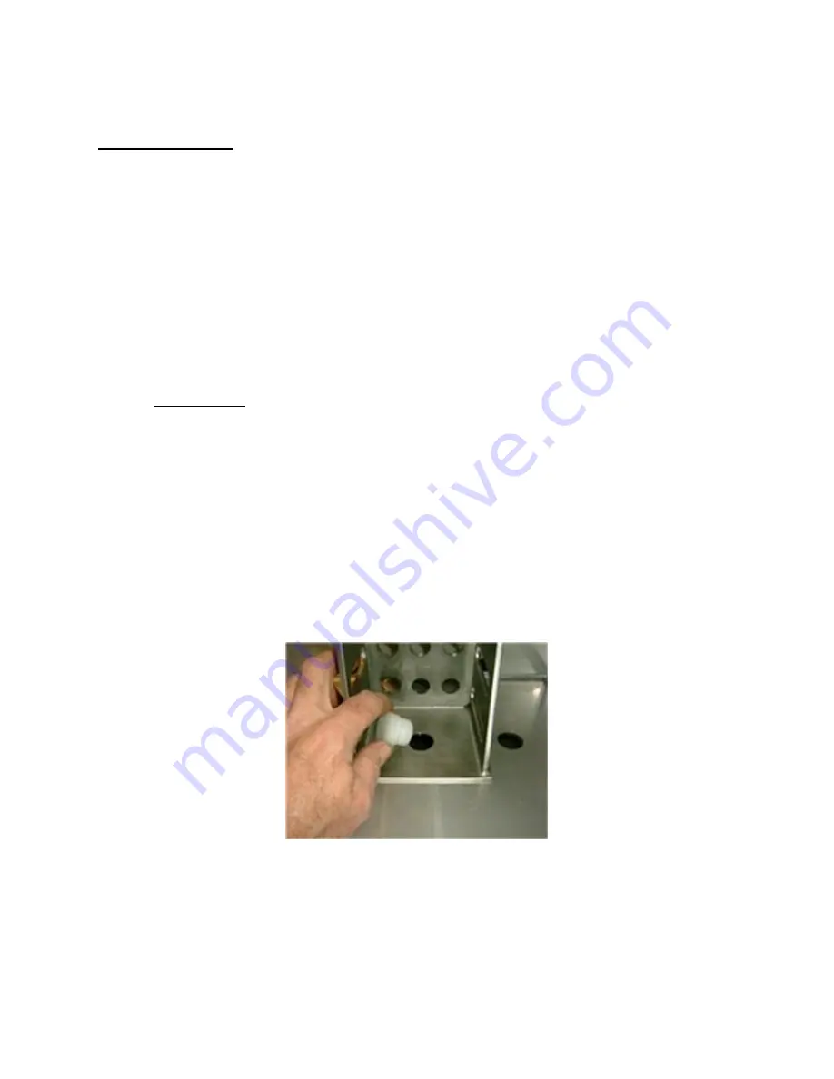
PET BOTTLE HOLDERS
If PET bottles are used on the filler, a special adaptor is placed on the filler base instead of the glass
bottle holders (pucks). PET bottles are held by the neck to withstand the force applied by the filling head.
The PET adaptor is held in place by a plastic plug which locates the adaptor to the filler base (see picture
below). Align the hole in the adaptor with the center hole in the machine base.
Inserting PET adaptor plug


