214880
80
Revision A
4.5.3
Replacing Cutterbar Spindles
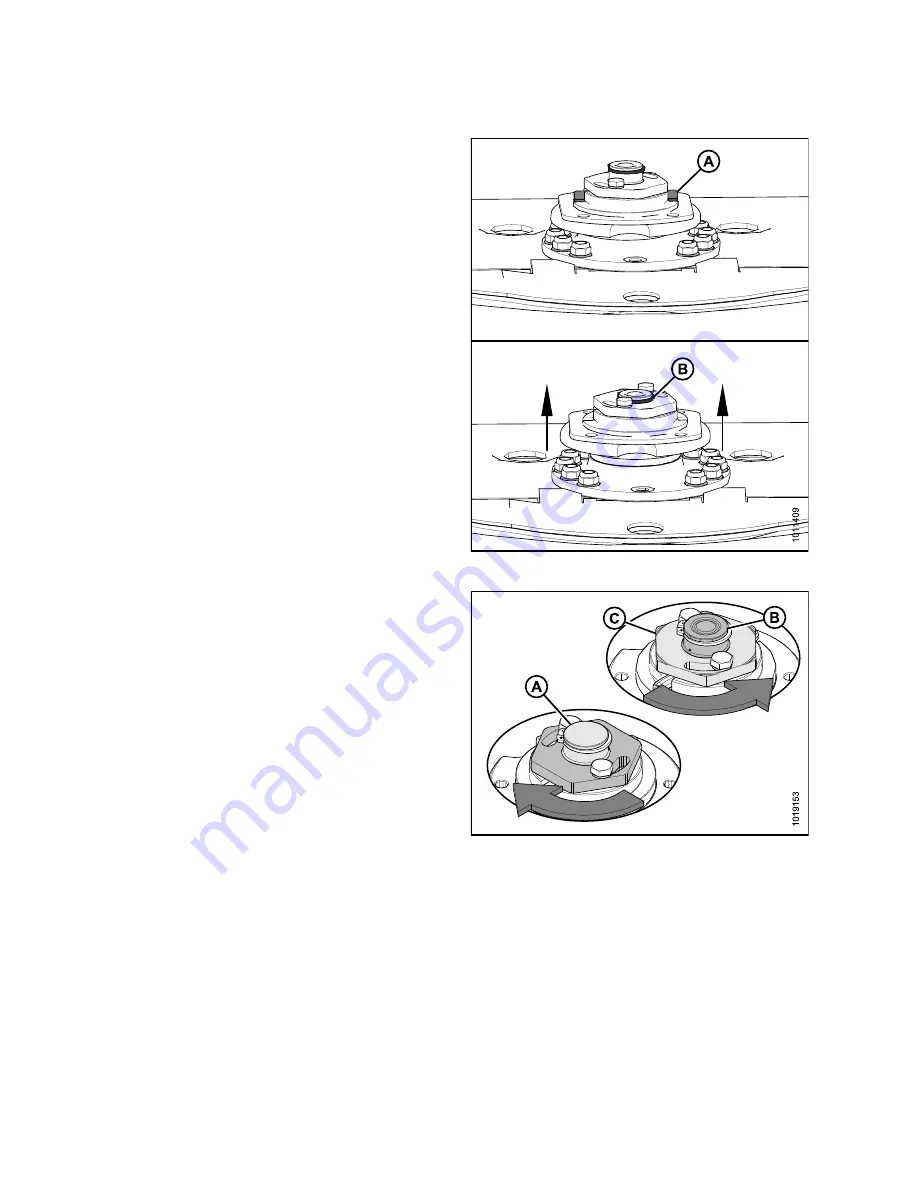
Figure 4.26: Cutterbar Spindles
To prevent damage to the cutterbar and drive systems, each
disc is attached to a spindle containing a shear pin (A).
If the disc contacts a large object such as a stone or stump, the
pin will shear and the disc will stop rotating and move upwards
while remaining attached to the spindle with a snap ring (B).
NOTE:
Once spindle has risen due to shear pin failure, the spindle
’
s
bearing will become unloaded. Do
NOT
replace the spindle due
to excessive play. Check play after torquing spindle nut and
replacing damaged shear pins.
Refer to
4.5.8 Replacing Cutterbar Spindle Shear Pin, page 116
to replace shear pin.
Figure 4.27: Cutterbar Spindles
IMPORTANT:
•
Spindles that rotate clockwise have right-leading threading
and are identified by a smooth top on the spindle gear
shaft (A).
•
Spindles that rotate counterclockwise have left-leading
threading and are identified by machined grooves on the
spindle gear shaft (B) and nut (C).
•
If spindle position in cutterbar has changed, the rotational
direction of that spindle
MUST
remain the same (that is, a
clockwise spindle must maintain its clockwise rotation).
•
Failure to maintain rotation pattern can result in damage to
spindle and/or cutterbar components.
•
Safecut (shear pin) will not work if spindles are used in the
wrong orientation.


