background image

5

SCCFG Users Manual  EM-9192 Rev.4

3.  MAIN DIALOG

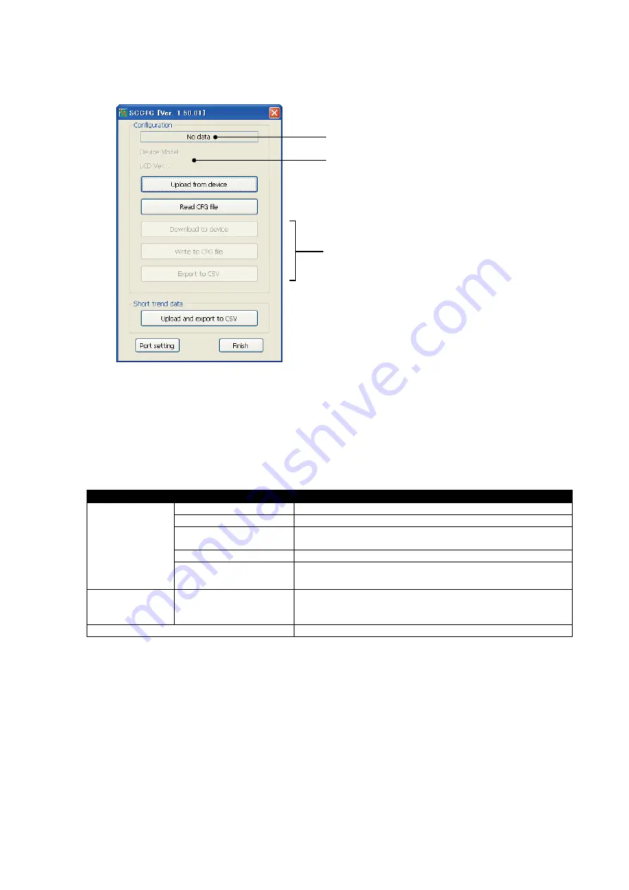
Double-clicking SCCFG.exe icon starts the SCCFG to show Main Dialog as shown below.

(1) “Uploaded from device” is indicated when [Upload from device] has been successfully completed.
 

File name is indicated when [Read CFG file] has been successfully completed.

(2) Device Model and LCD Ver. are indicated when [Upload from device] or [Read CFG file] has been successfully 

completed. (e.g. LCD Ver. : 1.0x)

(3) The buttons become selectable once [Upload from device] or [Read CFG file] is complete.

MAIN DIALOG MENU 

Configuration

Upload from device

Setting data is uploaded from the Controller via infrared communication.

Read CFG file

Setting data is read in from a file.

Download to device

Setting data is download to the Controller via infrared communication.

New setting is valid only after the power supply is restarted.

Write to CFG file

Setting data is saved in a file.

Export to CSV

Setting data is converted into CSV and saved.

Short trend data

Upload and export to CSV

Short trend data is acquired from the device via infrared and saved as 
CSV file. 
Error occurs with models SC100 or SC110.

COM Port

COM port for infrared communication is specified.

(1)

(2)

(3)

Summary of Contents for SC100 Series

Page 1: ...00 SC200 Series Multi Function PID Controller PC CONFIGURATOR SOFTWARE Model SCCFG Users Manual http www m system co jp 5 2 55 Minamitsumori Nishinari ku Osaka 557 0063 JAPAN Tel 81 6 6659 8201 Fax 81 6 6659 8510 E mail info m system co jp ...

Page 2: ... COMMUNICATION ADAPTOR 6 4 4 SETTING ON THE CONTROLLER 6 5 COM PORT SETTING 7 6 CONFIGURATION 8 6 1 UPLOAD FROM DEVICE 8 6 2 READ CFG FILE 8 6 3 DOWNLOAD TO DEVICE 8 6 3 1 WRITE TO DEVICE WITH DIFFERENT LCD FIRMWARE VERSION 9 6 4 WRITE TO CFG FILE 10 6 5 EXPORT TO CSV 10 6 6 CONFIGURATION DATA IN CSV FORMAT 11 6 7 CONFIGURATION ITEM LIST 19 7 SHORT TREND DATA 22 7 1 UPLOAD AND EXPORT TO CSV 22 7 2...

Page 3: ...a tion methods Please refer to the relevant hardware users manuals for the detailed information about the terms used in this manual The SCCFG makes it easy and smooth to set parameters to the SC100 200 Series Setting data and short trend data can be exported to CSV file via infrared communication LCD firmware version mentioned in the text can be confirmed on the screen of the Controller Go to Conf...

Page 4: ...unication Only binary format file can be transferred Creating short trend data files Short trend data file received from the Controller via infrared is converted into CSV and saved SC200 SC210 SC200D SC200W and SC210W only 2 2 SYSTEM REQUIREMENTS PC IBM PC AT or compatible OS Windows XP SP3 or later Windows Vista Windows 7 32 bit 64 bit Windows 10 32 bit 64 bit Note no guarantee for all environmen...

Page 5: ...or Read CFG file is complete MAIN DIALOG MENU Configuration Upload from device Setting data is uploaded from the Controller via infrared communication Read CFG file Setting data is read in from a file Download to device Setting data is download to the Controller via infrared communication New setting is valid only after the power supply is restarted Write to CFG file Setting data is saved in a fil...

Page 6: ... to the users manual for the Controller for more information to operate the Controller to activate the communica tion mode 4 3 COP US COMMUNICATION ADAPTOR Use M System s Model COP US to communicate with the Controller with wired communication Before using the COP US install its driver in your PC Refer to the instruction manual for the COP US for more information When the driver is installed corre...

Page 7: ...7 SCCFG Users Manual EM 9192 Rev 4 5 COM PORT SETTING Select COM No assigned to the COP IRDA or COP US among COM1 to COM20 ...

Page 8: ...he table below shows relevant parameters PARAMETER Write X Back light brightness X Screen saver time X MV 0 100 symbol X Loop display MV OP X Loop variables X Graph scale divisions X Decimals display X Alarm blinking X Bargraph color X Digital display color X Trend recording X Storing interval X Trend channel X Trend graph color X Selected loop color X Touch tone X Home X Select operation view X S...

Page 9: ... the data can be handed over even LCD firmware is different When reading configuration of LCD firmware version 1 3x or 1 4x and writing to the device with LCD firmware version 1 5x or later LCD firmware version of read data Ver 1 3x SC100 SC110 SC200 SC210 Ver 1 4x SC100 SC110 SC200 SC210 LCD firmware version of destination device Ver 1 5x or later CONFIGURATION ITEM DATA User s parameter table it...

Page 10: ... 4 WRITE TO CFG FILE Click on Write to CFG file The folder directory appears on the screen Type the name and click on Save 6 5 EXPORT TO CSV Click on Export to CSV The folder directory appears on the screen Type the name and click on Save ...

Page 11: ...ormal 13 MV1 Hi limit 12 MV1 Lo limit 14 MV2 Normal 13 MV2 Hi limit 12 MV2 Lo limit 14 Digital display color PV1 16 PV2 16 SP1 16 SP2 16 MV1 16 MV2 16 FN1 16 FN2 16 FN3 16 FN4 16 Trend recording Start Storing interval 10 sec Trend channel LP1 CH1 PV1 LP1 CH2 SP1 LP1 CH3 MV1 LP1 CH4 None LP2 CH1 PV2 LP2 CH2 SP2 LP2 CH3 MV2 LP2 CH4 None Trend graph color LP1 CH1 1 LP1 CH2 4 LP1 CH3 5 LP1 CH4 8 LP2 C...

Page 12: ... 10000 0 2 Unit Disable Name 0 0 10000 0 2 Unit Disable Name 0 0 10000 0 2 Unit Disable Name 0 0 10000 0 2 Unit Disable Name 0 0 10000 0 2 Unit Disable Name 0 0 10000 0 2 Unit Disable Name 0 0 10000 0 2 Unit Disable Name 0 0 10000 0 2 Unit Disable Name 0 0 10000 0 2 Unit Disable Name 0 0 10000 0 2 Unit Disable Name 0 0 10000 0 2 Unit Disable Name 0 0 10000 0 2 Unit Disable Name 0 0 10000 0 2 Unit ...

Page 13: ...mit 14 MV2 Normal 13 MV2 Hi limit 12 MV2 Lo limit 14 Digital display color PV1 16 PV2 16 SP1 16 SP2 16 MV1 16 MV2 16 FN1 16 FN2 16 FN3 16 FN4 16 Trend recording Start Storing interval 10 sec Trend channel LP1 CH1 PV1 LP1 CH2 SP1 LP1 CH3 MV1 LP1 CH4 None LP2 CH1 PV2 LP2 CH2 SP2 LP2 CH3 MV2 LP2 CH4 None Trend graph color LP1 CH1 1 LP1 CH2 4 LP1 CH3 5 LP1 CH4 8 LP2 CH1 1 LP2 CH2 4 LP2 CH3 5 LP2 CH4 8...

Page 14: ...2 Unit 10000 0 2 Disable Name 0 0 10000 0 2 Unit 10000 0 2 Disable Name 0 0 10000 0 2 Unit 10000 0 2 Disable Name 0 0 10000 0 2 Unit 10000 0 2 Disable Name 0 0 10000 0 2 Unit 10000 0 2 Disable Name 0 0 10000 0 2 Unit 10000 0 2 Disable Name 0 0 10000 0 2 Unit 10000 0 2 Disable Name 0 0 10000 0 2 Unit 10000 0 2 Disable Name 0 0 10000 0 2 Unit 10000 0 2 Disable Name 0 0 10000 0 2 Unit 10000 0 2 Disab...

Page 15: ...Hi limit 12 MV2 Lo limit 14 Digital display color PV1 16 PV2 16 SP1 16 SP2 16 MV1 16 MV2 16 FN1 16 FN2 16 FN3 16 FN4 16 Trend recording Start Storing interval 10 sec Trend channel LP1 CH1 PV1 LP1 CH2 SP1 LP1 CH3 MV1 LP1 CH4 None LP2 CH1 PV2 LP2 CH2 SP2 LP2 CH3 MV2 LP2 CH4 None Trend graph color LP1 CH1 1 LP1 CH2 4 LP1 CH3 5 LP1 CH4 8 LP2 CH1 1 LP2 CH2 4 LP2 CH3 5 LP2 CH4 8 Selected loop color 7 To...

Page 16: ...0000 0 2 Disable Name 0 0 10000 0 2 Unit 10000 0 2 Disable Name 0 0 10000 0 2 Unit 10000 0 2 Disable Name 0 0 10000 0 2 Unit 10000 0 2 Disable Name 0 0 10000 0 2 Unit 10000 0 2 Disable Name 0 0 10000 0 2 Unit 10000 0 2 Disable Name 0 0 10000 0 2 Unit 10000 0 2 Disable Name 0 0 10000 0 2 Unit 10000 0 2 Disable Name 0 0 10000 0 2 Unit 10000 0 2 Disable Name 0 0 10000 0 2 Unit 10000 0 2 Disable Name ...

Page 17: ...V2 Hi limit 12 MV2 Lo limit 14 Digital display color PV1 16 PV2 16 SP1 16 SP2 16 MV1 16 MV2 16 FN1 16 FN2 16 FN3 16 FN4 16 Trend recording Start Storing interval 10 sec Trend channel LP1 CH1 PV1 LP1 CH2 SP1 LP1 CH3 MV1 LP1 CH4 None LP2 CH1 PV2 LP2 CH2 SP2 LP2 CH3 MV2 LP2 CH4 None Trend graph color LP1 CH1 1 LP1 CH2 4 LP1 CH3 5 LP1 CH4 8 LP2 CH1 1 LP2 CH2 4 LP2 CH3 5 LP2 CH4 8 Selected loop color 7...

Page 18: ...0000 0 2 Disable Name 0 0 10000 0 2 Unit 10000 0 2 Disable Name 0 0 10000 0 2 Unit 10000 0 2 Disable Name 0 0 10000 0 2 Unit 10000 0 2 Disable Name 0 0 10000 0 2 Unit 10000 0 2 Disable Name 0 0 10000 0 2 Unit 10000 0 2 Disable Name 0 0 10000 0 2 Unit 10000 0 2 Disable Name 0 0 10000 0 2 Unit 10000 0 2 Disable Name 0 0 10000 0 2 Unit 10000 0 2 Disable Name 0 0 10000 0 2 Unit 10000 0 2 Disable Name ...

Page 19: ... to blink during PV and or MV alarms Bargraph color PV1 norm 18 colors color chart 1 5 PV1 bargraph color normal range PV1 Hi 1 PV1 bargraph color high alarm range PV1 Lo 4 PV1 bargraph color low alarm range PV2 norm 5 PV2 bargraph color normal range PV2 Hi 1 PV2 bargraph color high alarm range PV2 Lo 4 PV2 bargraph color low alarm range SP1 norm 8 SP1 bargraph color normal range SP2 norm 8 SP2 ba...

Page 20: ...argraph Enable Dual loop bargraph Enable Short trend Enable User s parameter table Enable Select unit mode Digital Selectable Eng unit Selectable Scale setting for PV indicators Bargraph Selectable Eng unit Selectable PRG mode indicator ON OFF ON ON OFF the program mode ITEM 01 of Func tion Block Numerical key control SP1 Disable Enable Enable Disable Enable the numerical key control for SP and MV...

Page 21: ...ngineering unit data s lower range value Decimal place 3 0 to 5 2 Engineering unit data s decimal point position DATA Hi limit 32000 10000 DATA s upper range value DATA Lo limit 32000 0 DATA s lower range value DATA decimal point position 0 to 5 2 DATA s decimal point position DATA engineering unit Max 8 characters Unit DATA s engineering unit 1 Color chart 2 Storing interval and timing INTERVAL T...

Page 22: ...1 UPLOAD AND EXPORT TO CSV Click on Upload and export to CSV to start communicating with the Controller via infrared Once the communication is established the folder directory appears on the screen Enter file name and click on Save button to create a CSV file ...

Page 23: ... of 8 channels are available Example PID function block for the primary loop is defined that for the secondary loop is not used The secondary loop short trend is not shown on the screen but data can be stored TREND CHANNEL SIGNAL TYPE DATA STORAGE GRAPH PLOTTING LP1 CH1 PV1 Yes Yes LP1 CH2 SP2 Yes LP1 CH3 MV1 Yes LP1 CH4 None LP2 CH1 FN1 Yes No LP2 CH2 FN2 Yes LP2 CH3 FN3 Yes LP2 CH4 FN4 Yes Tag N...

Page 24: ...in the defined format Device error 01 The SCCFG failed in writing setting data to the device 02 Setting data is not in the defined format 03 Setting data is not supported by the device 04 Setting data value is out of defined range Short trend data Illegal data The SCCFG failed in reading illegal trend data Unsupported device The SCCFG tried to read trend data from unsupported device other than SC2...

Reviews: