85
SC100/200 Series Function Block Application Manual EM-6460-C
6. SEQUENTIAL CONTROL BLOCK
6.1 GENERAL DESCRIPTIONS
A sequential control block uses switches and status signals from other blocks to condition and control various discrete sig-
nals. All ON/OFF signals must be controlled via sequential control blocks.
16 types of commands are available for use in relay sequence or in step sequence descriptions. They are registered in 12
sequential control blocks.
[Caution]
In this manual, switch or status ‘1’ is described ‘ON’ and ‘0’ is ‘OFF.’
6.1.1 CONFIGURATION OF SEQUENTIAL CONTROL BLOCKS
■
GENERAL CONFIGURATIONS
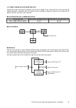
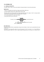
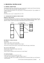
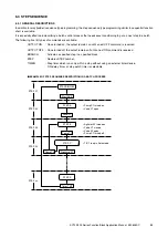
12 sequential control blocks (groups) are available per controller module. Each block can contain 89 commands at the maxi-
mum. Each block is divided into 20 steps (00 to 19), and can be connected with BRANCH command to realize a series of
sequence commands. A specific step in one block can be launched by a command from another block.
■
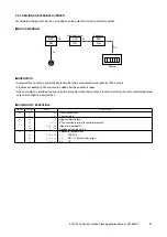
COMMANDS TO CONTROL THE BLOCK
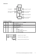
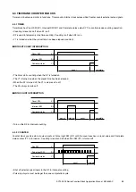
[S1 : Run SW]
• With S1 turned on, Steps 00 and 01 start operating.
• With S1 turned off, the operation is stopped and returns to Step 01.
• With cold start setting, only Steps 00 and 01 in Group 81 operate while all other groups are deactivated.
[S2 : Cancel ‘Go to Next Step’ SW]
• With S2 turned on, the operation is stopped. Output is held.
• Step 00 continues running.
• With S2 turned off, the operation starts at the step where it has been stopped.
[Y1 : Step Timer Complete]
• Set timer command in the step to ‘step watch timer’ mode.
• In this mode, when the step operation is complete, the output Y1 turns to ‘1.’
• The signal is used to detect errors of controlled hardware device when the control process does not go to next step after a
certain time period.
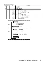
STEP 00
STEP 01
STEP 02
Step Sequence
Relay Sequence
00...19 Steps per Group
(max. 89 commands in total)
12 Groups
Commands
STEP 19
END
G81
G82
G92
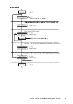
STEP 00

