the
jacket
must
be
supported
from
the
bo om
by
a
ledge
on
each
side
or
a
full
deck
beneath
the
jacket.
Pay
special
a en on
to
the
provisions
shown
for
gas
‐
line
hookup.
The
enclosure
should
have
ven la on
holes
to
prevent
gas
build
‐
up
in
the
event
of
a
leak.
The
deck
ledges
and
counter
should
be
fl
at
and
level.
(refer
to
ANSI
z21.58
Standard
for
Out
‐
door
Cooking
Gas
Appliances,
Sec on
1.7
Enclosures
For
Self
‐
Contained
LP
‐
Gas
Supply
Systems).
Keep
the
ven la on
open
‐
ings
of
the
cylinder
enclosure
free
and
clear
from
debris.
This
grill
requires
that
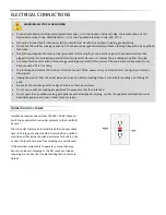
a
120
‐
volt,
60
hertz,
15
amp
GFI
‐
cer
fi
ed
outlet
be
installed
by
a
quali
fi
ed
electrician.
One
way
to
safely
move
the
grill
o
ff
the
pallet
is
by
li ing
one
end
of
the
grill
high
enough
to
place
a
ramp
under
the
wheel
and
then
li
the
other
end
while
rolling
the
grill
o
ff
the
pallet.
BEFORE
YOU
START…
(Con nued)
The
SmartGrill
by
Lynx
TM
built
‐
in
grill
is
designed
for
easy
installa on
into
masonry
enclosures.
NOTE:
Lynx
built
‐
in
SmartGrill
by
Lynx
TM’
are
intended
either
for
installa on
in
a
built
‐
in
enclosure
constructed
of
non
‐
combus ble
material
or
for
an
installa on
to
a
built
‐
in
enclosure
constructed
of
combus ble
material
when
installed
with
a
Lynx
Insula ng
Jacket
(LIJ)
R
e
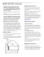
Remove
all
e
‐
downs
INTERIOR
PACKING
BUILT
‐
IN
INSTALLATIONS
Lynx
uses
sturdy
e
‐
down
cables
and
straps
to
ensure
your
grill
arrives
at
your
home
in
the
same
condi on
that
it
le
our
factory.
BE
SURE
YOU
HAVE
REMOVED
ALL
TIE
DOWNS
BEFORE
USING
YOUR
GRILL.
Make
sure
you
remember
to
remove
the
e
downs
on
the
burners
Ensure
the
burners
are
properly
seated
on
the
burner
valve
ori
fi
ce
and
si ng
level
with
the
legs
in
the
frame
slots
and
have
no
side
‐
to
‐
side
movement.
Remove
any
loose
items
from
the
packaging,
drip
tray
and
the
fi
rebox.
For
non
‐
combus ble
applica ons,
the
grill
drops
into
the
opening
shown
in
the
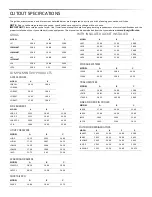
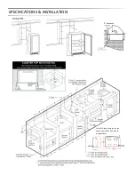
cutout
detail
drawing
(See:
“Gas
re
‐
quirements”)
and
hangs
from
its
counter
‐
top
trim.
A
deck
is
not
required
to
support
it
from
the
bo om.
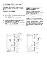
When
using
the
insulated
jacket
in
a
combus ble
enclosure,
CLEARANCE
TO
COMBUSTIBLE
MATERIALS
Non
‐
combus ble
materials
may
make
direct
contact
with
the
edges
of
the
fi
rebox
body
up
to
the
top
surface
of
the
fi
rebox.
Below
the
counter
top
surface
the
non
‐
combus bles
should
not
encroach
on
the
cutout
dimen
‐
sions
de
fi
ned
in
this
manual
for
both
fi
t,
access
to
service
and
air
fl
ow.
Above
the
counter
top
a
minimum
clearance
of
6”
is
needed
on
the
le
side
of
the
smoker
for
the
motor
and
skewer
if
you
have
a
ro sserie
model
smoker.
At
least
6”
of
clearance
on
the
right
side
is
recommended
as
well.
A
3
inch
clearance
is
required
immediately
behind
the
smoker
to
allow
the
front
hood
to
open.
The
smoker
exhausts
combus
‐
on
products
and
cooking
greases
to
the
back
of
the
unit.
Nev
‐
er
locate
the
smoker
where
this
residue
will
be
di
ffi
cult
to
clean.
Any
non
‐
combus ble
overhead
surfaces
must
be
at
least
6
feet
above
the
counter
top
surface.
A
vent
hood
may
be
closer
to
the
counter
top
surface
than
6
feet.
CLEARANCE
TO
NON
‐
COMBUSTIBLE
MATERIALS
Minimum
clearance
to
the
sides
and
back
of
the
grill
to
adja
‐
cent
combus ble
construc on
below
the
counter
‐
top
surface
is
12”
from
the
sides
and
back.
Dégagement
minimal
entre
les
parois
laterals
et
l’arrière
de
l’appareil
et
la
construc on
combus ble
au
‐
dessous
du
pan
‐
neau
supérieur
de
l’appareil
(30cm
a
par r
des
parois
laterals
et
30cm
a
par r
de
l’arrière).
Minimum
clearance
from
sides
and
back
of
smoker
to
adjacent
combus ble
construc on
extending
above
the
counter
top
surface
is
18”
from
the
sides
and
back.
Summary of Contents for SMART30
Page 1: ...SMARTGRILL USER MANUAL...
Page 2: ...SmartGrill by LynxTM...
Page 35: ...WIRING DIAGRAMS 30 SmartGrill Electrical Diagram...
Page 36: ...WIRING DIAGRAMS 36 and 42 SmartGrill Electrical Diagram...
Page 37: ...EXPLODED PARTS DIAGRAMS...
Page 38: ...EXPLODED PARTS DIAGRAMS...
Page 39: ...EXPLODED PARTS LIST...
Page 40: ...EXPLODED PARTS LIST AND DIAGRAMS...
Page 41: ...EXPLODED PARTS LIST AND DIAGRAMS...
Page 42: ...EXPLODED PARTS LIST AND DIAGRAMS...
Page 47: ......

