background image

Reference Manual P MX 3312/3313 D Version1.3


Page 9  


Functional Diagram 

Figure 1 below is the basic functional diagram for 
the P MX 3312/3313 D MiniModule. 


Figure 1- P MX 3312/3313 D Functional Diagram 


Module Layout 

Figure 2 shows the physical layout of the P MX 

3312/3313 D MiniModule. Video I/O is made 

through standard 75 Ohm BNC video connections 

and the balanced audio inputs are made on the 
Sub D connector. Module configuration is set via a 

small dip-switches located behind access holes in 

the bottom of the module. 
 

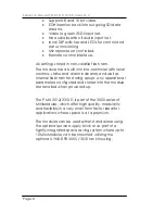
If the module is being used in a stand alone 

application then the optional power supply (R PS 
3001 E, PS 3001 U or R PS 3001-3) is required to 

power the module (not shown) 


Audio A to D

Conversion

Audio A to D

Conversion

Audio Group

Insertion

PLL

SER

PAR

EDH

Insertion

PAR

SER

Alarm

Status 1..4

Switch

Remote

Micro Controller

Switch

SDI IN

SDI out 1

SDI out 2

SDI out 3

SDI out 4

A2 L/R

A1 L/R


Summary of Contents for P MX 3312 D

Page 1: ...Germany www lynx technik com Reference Manual P MX 3312 3313 D Dual Analog Audio Multiplexer MiniModules Dual Analog Audio Multiplexer P MX 3312 D n c SDI IN SDI out 1 SDI out 2 SDI out 3 Audio in SDI...

Page 2: ...ss written permission of LYNX Technik AG LYNX Technik AG may have patents patent applications trademarks copyrights or other intellectual property rights covering the subject matter in this document E...

Page 3: ...warranty shall not apply to any defect failure or damage caused by improper use or improper or inadequate maintenance and care LYNX Technik shall not be obligated to furnish service under this warran...

Page 4: ...is operated in a commercial environment This equipment generates uses and can radiate radio frequency energy and if not installed and used in accordance with the instruction manual may cause harmful i...

Page 5: ...1 Audio Input Connections balanced 11 Power Connections 12 DC Power Connector 12 Installation 13 Mechanical 13 Stand Alone Operation 13 Multiple Units 14 Electrical Installation 15 Stand Alone Operati...

Page 6: ...Reference Manual P MX 3312 3313 D Version1 3 Page 6 This Page is intentionally left blank...

Page 7: ...group and multiplexes this into the incoming SDI video input Group insertion is selectable 1 through 4 Four separate SDI outputs of the video with embedded audio are provided Existing audio groups can...

Page 8: ...cal controls status and alarm indicators and well as internal flash ram for storing setups Any operational parameters configured and stored into the module are recalled when powered up The P MX 3312 3...

Page 9: ...he balanced audio inputs are made on the Sub D connector Module configuration is set via a small dip switches located behind access holes in the bottom of the module If the module is being used in a s...

Page 10: ...Reference Manual P MX 3312 3313 D Version1 3 Page 10 Figure 2 Module Layout...

Page 11: ...itable for digital video audio connections to reduce the risk of interference or errors due to excessive cable attenuation Note Due to the compact design of the module it will be necessary to use a co...

Page 12: ...e MiniModule has a captive power lead fitted to the module with a male 5 pin locking bayonet connector This connection provides DC power and also data connectivity to the module Connector wiring is sh...

Page 13: ...e R FR 3010 option is required to power each module Please refer to the R FR 3005 Reference Manual supplied with this option for more details b Single Use The MiniModule can be powered independently w...

Page 14: ...the R FR 3005 Reference Manual for more details b Using the R FR 3010 Rack frame extension option Can be combined with the R FR 3005 Rack frame option Each module plugs into a connection bus which pro...

Page 15: ...onnection is solid and locked in place A strain relief is included within the module to prevent excessive strain on the connection Signal connections should be made with care please ensure connections...

Page 16: ...6 Multiple Units When installing multiple MiniModule units it is recommended you use the R FR 3005 Rack Frame 1 and or R FR 3010 Rack Frame 2 options Please refer to the documentation supplied with th...

Page 17: ...bled ON 24 bit AES output 2 OFF 20 bit AES output ON Delete ALL incoming embedded AES audio 3 OFF ONLY replace Audio group selected with SW2 SW 3 Position Set Function ON Audio Group 1 selected 1 OFF...

Page 18: ...ich means 18dBu P MX 3312 or 24dBu P MX 3313 OFF selects the low range 12dBu or 15dBu P MX 3312 or 15dBu or 18dBu P MX 3313 depending on the selection of switch 2 Dip Switch 2 Select full scale range...

Page 19: ...module This is because all settings can be changed from the remote control system or via the Service Adapter This overrides the local dip switches regardless of Switch 1 ON OFF setting To ensure the m...

Page 20: ...which was present on the incoming SDI signal will pass transparently SW 2 Dip Switch 4 No function here SW3 Dip Switch 1 through 4 Select Audio Groups These four switches are used to select which audi...

Page 21: ...3312 D ON Select High Range 0 dB FS Level P MX 3312 D 2 ON 15 dBu P MX 3312 D 24 dBu P MX 3312 D 3 OFF Normal operation channel 1 no mute 4 OFF Normal operation channel 2 no mute Switch 2 1 ON Local a...

Page 22: ...cation states Note When working in 525 mode with 24 Bit audio selected then only the first three groups can be embedded Group 4 is locked In 525 mode with 20 bit audio all four groups are accessible L...

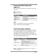
Page 23: ...n in installations where visible access to the bottom of the module is not convenient This LED is three color and has several indication states Note LED OFF indicates power is lost or there is a power...

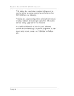
Page 24: ...ote controller or the RCT 3000 Service Adapter Example of user configuration error is the module is trying to insert an audio group but no AES audio data is being supplied to the module Some examples...

Page 25: ...ectable P MX 3313 D Outputs Signal 4 x SDI 4 2 2 SMPTE 259M CD 270 360 Mbps with EDH Connection BNC Impedance 75 Ohms Jitter 0 2 UI Operating Modes Embedding Embed audio 2 x analog stereo audio one gr...

Page 26: ...MiniModules 110 240 VAC input 5V DC output R FR 3004 4 Module mounting frame This is a small mechanical mounting bracket for 4 MiniModules Can be mounted with screws on any surface R FR 3005 Rack Fra...

Page 27: ...l Audio Multiplexer Model Number P MX 3313 D Part Number 6 155 002 296 Service If you are experiencing problems or have questions concerning your P MX 3312 3313 D MiniModule please contact your local...

Page 28: ...YNX Technik can be contacted directly using the information below Address LYNX Technik AG Brunnenweg 3 64331 Weiterstadt Germany Website www lynx technik com E Mail info lynx technik com LYNX Technik...

Page 29: ...Reference Manual P MX 3312 3313 D Version1 3 Page 29 This Page is intentionally left blank...

Page 30: ...Reference Manual P MX 3312 3313 D Version1 3 Page 30 Notes...

Reviews: