background image

CONTROLS/INSTRUMENTS/EQUIPMENT

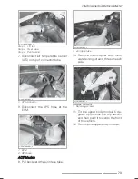
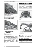
20) Holding Strap

BoonDocker Series

Holding strap provides a grip for opera-
tor when side-hilling.

WARNING

This strap is not for towing, lift-
ing or other purpose than tempo-
rary use as a grab handle during
side-hilling. Always keep at least
one hand on handlebar.

21) Side Panels

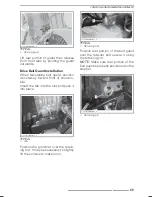
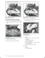
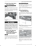
To open a side panel, push the buttons.

fmo2014-001-006_a

TYPICAL

1. Buttons

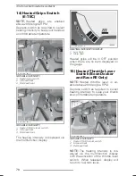
To close a side panel, set firmly on the
stud location and push side panel locks
to make sure it is secured.

Make sure lower front edge of the side
panel goes to its right place and side
panel is align.

fmo2014-002-023_a

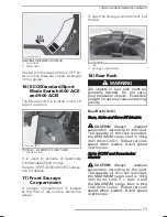
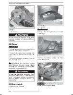
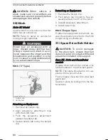
To remove a side panel, open it then lift
it up. Free the lower hinge from its slot,
then free the upper hinge by lowering
the panel.

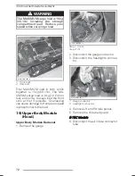
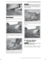
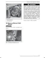
To install a side panel, insert the upper
hinge and then the lower hinge.

fmo2014-002-006_a

1. Upper hinge
2. Lower hinge

Close the side panel.

_______________

75

Summary of Contents for 800R E-TEC

Page 1: ...fety information Minimum recommended operator s age 16 years old Keep this Operator s Guide in the vehicle EN 619 950 590 Original instructions 2017 2017 OPERATOR S GUIDE REX2 Sport Deep Snow Sport Crossover REX 2 Sport Deep Snow Sport Crossover EN 2017 ...

Page 2: ...ocker RE 3700 800R E TEC BoonDocker 3900 600 E TEC BoonDocker 3900 800R E TEC BoonDocker DS 3900 800R E TEC BoonDocker DS 4100 800R E TEC CROSSOVER Xtrim 600 ACE Xtrim SC 600 E TEC Xtrim RE 3500 600 E TEC Xtrim RE 3500 800R E TEC Xtrim SC 900 ACE Lynx products are manufactured by BRP The following are trademarks of Bombardier Recreational Products Inc or its sub sidiaries ACE eDrive HPG LEARNING K...

Page 3: ...enska Denna bok kan finnas tillgänglig på ditt språk Kontakta din återförsäljare eller gå till www operatorsguides brp com Congratulations on your purchase of a new Lynx snowmobile Whatever model you have chosen it is backed by the Bombardier Recreational Products inc BRP warranty and a network of authorized Lynx snowmobile dealers ready to provide the parts service or accessories you may require ...

Page 4: ... the operator 1 UP refers to a model designed for an operator only 2 UP refers to a model designed to accommodate one passenger Keep this Operator s Guide in the vehi cle as you can refer to it for things such as maintenance troubleshooting and instructing others Note that this guide is available in sev eral languages In the event of any dis crepancy the English version shall pre vail If you want ...

Page 5: ...ition Reverse Operation 17 Carrying a Passenger 17 Terrain Riding Variations 19 Environment 22 Transporting and Towing 24 TRACTION ENHANCING PRODUCTS 25 Manoeuvrability 25 Acceleration 26 Braking 26 Important Safety Rules 26 Effects of Having a Studded Track on the Life of the Snowmobile 27 Installation of Studs on BRP Approved Tracks 27 Maintenance Replacement 28 IMPORTANT ON PRODUCT LABELS 29 Ha...

Page 6: ... 18 Rear Rack 71 19 Upper Body Module Hood 72 20 Holding Strap 75 21 Side Panels 75 22 Fuses 76 23 Seat Latch 76 24 Storage Battery Compartment 77 25 Front and Rear Bumpers 78 26 Brake disc guard 78 27 Anti Sway Bar Quick Disconnect Link 79 28 Electronic Damping Control LEDC Electronic Controlled Suspension ECS 79 29 Ice Scratchers BoonDocker DS 79 30 Hitch 80 31 Spare Drive Belt Holder 80 32 Reve...

Page 7: ... YOUR RIDE 96 Rear Suspension Adjustments 96 Front Suspension Adjustments 101 Adjustment Tips According to Vehicle Behavior 106 MAINTENANCE INFORMATION FIRST INSPECTION 110 MAINTENANCE SCHEDULE E TEC 113 MAINTENANCE SCHEDULE ACE 115 MAINTENANCE PROCEDURES 117 Air Filter with Dual Air Intake E TEC models 117 Engine Coolant 117 Engine Oil ACE 118 Engine Oil Filter ACE 120 Exhaust System 121 Spark Pl...

Page 8: ...TED STATES 146 DECLARATION OF CONFORMITY 147 RADIO FREQUENCY DIGITALLY ENCODED SECURITY SYSTEM RF D E S S KEY 148 SPECIFICATIONS 149 TROUBLESHOOTING TROUBLESHOOTING GUIDELINES 170 MONITORING SYSTEM 173 Pilot Lamps Messages and Beeper Codes 173 Fault Codes 176 WARRANTY BRP FINLAND OY INTERNATIONAL LIMITED WARRANTY 2017 LYNX SNOWMOBILES 178 MAINTENANCE RECORDS 181 CUSTOMER INFORMATION CONTACT US 186...

Page 9: ...SAFETY INFORMATION ________ SAFETY INFORMATION ________ 7 ...

Page 10: ...way from the en gine To reduce the risk of fire or explo sion follow these instructions Use only an approved gasoline con tainer to store fuel Strictly adhere to instructions in FU ELING PROCEDURE Never start or operate the engine if the fuel cap is not properly installed Gasoline is poisonous and can cause injury or death Never siphon gasoline by mouth If you swallow gasoline get any in your eye ...

Page 11: ...ning program Any new operator must read and understand all safety labels on the snowmo bile the Operator s Guide before operating the snowmobile Only allow a new operator to operate the snowmobile in a restricted flat area at least until he is completely familiar with its operation If snowmobile operator s training course is offered in your area have him enroll The performance of some snowmobiles ...

Page 12: ...stop then look carefully in both directions before crossing at a 90 angle Be wary of parked vehicles Snowmobiling at night can be a delightful experience but because of reduced visibility be extra cautious Avoid unfamiliar terrain and be sure your lights are working Always carry a flashlight and spare light bulbs Never remove any original equipment from your snowmobile Each vehicle has many built ...

Page 13: ...e is not in use Never run the engine in a non ventilated area and or if vehicle is left unattended Electric start models only Never charge or boost a battery while installed on snowmobile E TEC engines Never attempt any fuel system or electrical system main tenance or repair Any maintenance or repair of these systems must be performed by an authorized Lynx dealer Never attempt any fuel system or e...

Page 14: ...h 2 UP models the operator is responsible for the safety of the passenger Always remember that the snowmobile handling stability and brak ing distance may be affected when riding with a passenger Before riding the vehicle ask your passenger to inform you to slowdown or stop immediately if he feels uncomfortable or insecure during the ride Keep a watchful eye on your passenger while riding 12 _____...

Page 15: ...CO Mode When ECO mode is selected fuel economy mode vehicle torque and speed are limited whereby an optimal cruising speed is maintained in order to reduce fuel consumption Refer to OPERATING MODES subsec tion for detailed instructions Standard Mode In standard mode acceleration is re duced when accelerating from a com plete stop and when operating in the low vehicle speed range under certain cond...

Page 16: ...safe ride Pre Ride Inspection WARNING The pre operation check is very important prior to operating the vehicle Always check the proper operation of critical controls safety features and mechanical components before starting WARNING Always use a wide base snowmo bile mechanical stand to properly support vehicle during any track verification Slowly accelerate engine in order to rotate track at very ...

Page 17: ...IS AND STEERING ACTION Check for free movement and proper operation FUEL AND INJECTION OIL IF APPLICABLE Check for proper level and no leaks COOLANT Check for proper level and no leaks BRAKE FLUID Check for proper level and no leaks STORAGE COMPARTMENT Check for proper latching and no heavy or breakable objects TRACK Check condition and remove snow or ice For studded tracks see INSPECTION in the T...

Page 18: ...ools that can help him and others in an emergency First aid kit Provided tool kit Mobile phone Knife Spare spark plugs Flashlight Friction tape Trail map Spare drive belt Snack Include other items depending on the length and time of your ride Riding Position Forward Operation Your riding position and balance are the two basic principles of making your snowmobile go where you want it to When turnin...

Page 19: ...p fmo2008 003 004 Rider Position Reverse Operation We recommend sitting on your snow mobile when operating in reverse Avoid standing up Your weight could shift forward against throttle lever while operating in reverse causing an unexpected acceleration WARNING Unexpected acceleration when snowmobile operates in reverse can cause a loss of control Carrying a Passenger Certain snowmobiles are design...

Page 20: ... with passengers and the operator can sometimes see more of the trail ahead than the passengers Therefore smooth starting and stop ping are required with passengers and the operator must slow down The op erator must also warn passengers of side hills bumps branches etc An unforeseen bump can leave you pas senger less Remind your passengers to lean into the turn with you without causing the vehicle...

Page 21: ...teadily and slowly apply the throttle Depending on whether the front or rear end of the vehicle is sinking your feet should be placed on the opposing end of the run ning boards Never place foreign ma terial beneath the track for support Do not allow anyone to stand in front of or to the rear of the snowmobile with the engine running Stay away from the track Personal injury will result if con tact ...

Page 22: ... on the running board or the posting posi tion Be prepared to shift your weight quickly as needed Side hills and steep slopes are not recommended for a be ginner or a novice snowmobiler Slush Slush should be avoided at all times Always check for slush before starting across any lake or river If dark spots appear in your tracks get off the ice immediately Ice and water can be thrown rearward into t...

Page 23: ...ing on terrain conditions there are two preferred ways to turn or cor ner a snowmobile For most snow surfaces body english is the key to turning Leaning towards the inside of the turn and positioning body weight on the inside foot will create a bank ing condition beneath the track By adopting this position and positioning yourself as far forward as possible weight will be transferred to the inside...

Page 24: ... left turn is indicated by extending your left hand straight out in the proper direction For right turns extend the left arm and raise the hand to a vertical position so it forms a right angle at the elbow Every snowmobiler should relay any signal to the ones behind Trail Stops Whenever possible pull off the trail when you stop This will reduce the hazard to other snowmobilers using the trail Trai...

Page 25: ... how you ride a snowmobile You re a light treader when you follow the principles below Become informed Obtain maps reg ulations and other information from the Forest Service or from other pub lic land agencies Learn the rules and follow them and that goes for speed limits too Avoid running over young trees shrubs and grasses and don t cut wood On flatlands or areas where trail riding is popular it...

Page 26: ...biler You don t have to leave big tracks or careen through a virgin forest to show you can ride So whether you re driving a high perfor mance Lynx a sporty RS snowmo bile or any other make or model show you know what you re doing Show you know how to send snow flying and make tracks with a light touch Transporting and Towing Follow transporting and towing in structions explained further in this gu...

Page 27: ...on period If your snowmobile is equipped with traction enhancing products be sure to take plenty of time to get used to the way it handles when turning accelerating and braking Also always check local regulations concerning the use of traction enhanc ing products on snowmobiles Always drive your snowmobile in a responsible manner respecting the environment and other people s property Manoeuvrabili...

Page 28: ...id This could cause debris or ice to be thrown violently backwards pos sibly injuring others nearby or on snowmobiles behind you Braking As in the case of acceleration using studs on the track will give you better braking capacity on packed snow or ice but will have no noticeable effect on soft snow Braking may thus vary suddenly under certain conditions Be sure to use restraint in braking to keep...

Page 29: ...rn or not installed the gas tank could be punctured causing a fire NOTICE Ask your dealer for the appropriate tunnel protectors model and kit number required for your snowmobile NOTE Consult the BRP limited war ranty to find out what warranty limita tions are related to the use of studs Installation of Studs on BRP Approved Tracks WARNING Never stud a track that has not been approved for studs Ap ...

Page 30: ...mportant to follow the torque specifications for the stud bolts INSTALLING AN INCORRECT NUMBER OF STUDS OR AN IM PROPER INSTALLATION CAN IN CREASE THE RISK OF THE TRACK TEARING OR SEVERING Maintenance Replacement PROCEED WITH A VISUAL INSPEC TION OF YOUR TRACK BEFORE EACH USE Look for any defects such as Perforations in the track Tears in the track particularly around traction holes on studded tra...

Page 31: ...ent qui assurera une performance une efficacité et une fiabilité optimales à long terme Durant la période de rodage le moteur consommera plus d huile et d essence qu à la normale Ainsi il se peut que le moteur ait des ratés Cela est normal puisque le module de commande protège le moteur contre l usure prématurée et assure un rodage optimal Après cette période qui dure environ 2 pleins d essence 80...

Page 32: ...hould be considered permanent parts of the vehicle If missing or damaged the decals can be replaced free of charge See an authorized Lynx dealer NOTE In the event of any discrepancy between this guide and the vehicle the safety labels on the vehicle have precedence over the labels in this guide fmo2014 001 012_e fmo2014 001 006_f TYPICAL fmo2015 001 005_a TYPICAL Label 1 516006903 LABEL 1 ON LEFT ...

Page 33: ...Beware of hot vapors Do not use without pulley guard Beware of drive belt Read instructions before ser vice 516003919 LABEL 2 ON PULLEY GUARD Label 3 516006900 en LABEL 3 ON PULLEY GUARD AND ON BRAKE DISC GUARD Label 4 516004607 LABEL 4 ON LEFT SIDE PANEL Label 5 fmo2014 001 017 LABEL 5 ON SHOCK ________ SAFETY INFORMATION ________ 31 ...

Page 34: ... 7 mmo2013 004 046_a LABEL 7 ON FUEL INJECTORS E TEC MODELS Label 8 CAPACITOR Capacitor May Spark If Shorted Spark can ignite fuel vapors Keep objects away from poles When removing from vehicle always discharge properly 516006206 LABEL 8 E TEC ONLY 32 _______ SAFETY INFORMATION ________ ...

Page 35: ... Label 10 WARNING Always use a rigid tow bar to tow 516008282 EN 516008282 DEC LABEL 10 XTRIM SC L Label 11 5583A Always electrically disconnect both fuel injectors prior to testing for ignition spark Otherwise fuel vapors may ignite in presence of a spark creating a fire hazard 516005583A LABEL 11 ON E TEC MODELS L Label 12 516005521 LABEL 12 ON ACE MODELS ________ SAFETY INFORMATION ________ 33 ...

Page 36: ...T LABELS Label 13 WARNING Beware of rotating track 516007584 LABEL 13 Technical Information Labels fmo2014 001 013_d fmo2014 001 014_c fmo2014 002 019_a ACE MODELS fmo2014 001 013_a 34 _______ SAFETY INFORMATION ________ ...

Page 37: ...72 LABEL 2 E TEC MODELS 516006904 en LABEL 3 E TEC MODELS 516005503 LABEL 3 5447012 LABEL 4 ON RIGHT SIDE 516005507 LABEL 5 NEAR DRIVE PULLEY 800R E TEC 516007587 LABEL 6 RAVE SERIES 516007588 LABEL 6 XTRIM SERIES 516007589 LABEL 6 BOONDOCKER SERIES ________ SAFETY INFORMATION ________ 35 ...

Page 38: ...6343 LABEL 7 XTRIM STD AND SC AND BOONDOCKER 516006447 LABEL 7 XTRIM RE AND RAVE 95 A A V I S M ÉLANGE ÉTHANOL MA X 1 0 N O T I C E MAX10 ETHANOL B L E N D OCTANE mmo2013 002 004 LOCATED FUEL CAP 36 _______ SAFETY INFORMATION ________ ...

Page 39: ...VEHICLE INFORMATION _______________ 37 ...

Page 40: ...e models In these cases their reference numbers are deliberately missing in the illustrations NOTE Some vehicle safety labels are not shown on illustrations For information on vehicle safety labels refer to VEHICLE SAFETY LABELS subsection fmo2014 001 001_e TYPICAL fmo2016 001 004_a TYPICAL 38 ______________ ...

Page 41: ...ROLS INSTRUMENTS EQUIPMENT fmo2014 002 009_c XTRIM SC ONLY fmo2014 002 007_d XTRIM SC AND BOONDOCKER fmo2014 001 006_h TYPICAL fmo2014 001 019_c BOONDOCKER fmo2015 001 003_c LEDC RAVE RE _______________ 39 ...

Page 42: ...ight or left the skis are turned right or left to steer the snow mobile WARNING Fast reverse while turning could result in loss of stability and con trol 2 Throttle Lever Throttle Lever E TEC Models Throttle lever is located on the RH side of handlebar Designed to be thumb activated When squeezed it increases the en gine speed and engages the transmis sion When released engine speed returns automa...

Page 43: ...5 008 103_a TYPICAL WARNING Test the throttle lever operation each time before starting the en gine The lever must return to its the rest position once released Otherwise do not start engine Switching from Thumb to Finger Throttle Position CAUTION It is highly recom mended to immobilize the snowmo bile before attempting any modifi cation to the throttle position as it could lead to a hazardous sit...

Page 44: ...ake is applied When released it automatically re turns to the rest Braking effect is pro portional to the pressure applied on the lever and to the type of terrain and its snow coverage mmo2014 004 001_a TYPICAL 1 Brake lever 2 To apply brake 4 Parking Brake Lever Parking brake lever is located on the LH side of handlebar Parking brake should be used when ever snowmobile is parked mmo2014 004 001_b...

Page 45: ...l automatically return to its original posi tion Always release parking brake be fore riding mmo2007 009 037_b TYPICAL RELEASE MECHANISM Step 1 Step 1 Squeeze brake lever 5 Engine Tether Cut Out Switch The engine cut off switch tether cord is located to on the RH side of console The tether cord cap must be securely snapped on the engine cut off switch to allow vehicle operation General When the te...

Page 46: ...ap is free of dirt or snow D E S S Flexibility The ECM of your snowmobile can be programmed by your authorized Lynx dealer to accept 8 different keys We recommend the purchase of ad ditional tether cords from your au thorized Lynx dealer If you have more than one DESS equipped LynxLynx snowmobile each can be programmed by your authorized Lynx dealer to accept the other vehicles keys DESS Pilot Lam...

Page 47: ...ply the brake To restart button must be at the ON position up mmo2016 008 202_a OFF POSITION mmo2016 008 201_a ON POSITION All operators of the snowmobile should familiarize themselves with the function of this device by using it sev eral times on first outing and whenever stopping the engine thereafter This engine cut out procedure will become a reflex and will prepare operators for emergency sit...

Page 48: ...Mode set button Start Electronic Reverse Button Electric Start Models Press to start engine Refer to ENGINE STARTING PROCEDURE in the BASIC PROCEDURES subsection Electronic Reverse Models Once engine is started press to en gage the electronic reverse Refer to REVERSE RER in BASIC PROCE DURES section for procedure Headlights Dimmer Switch Press to select HI or LOW beam Lights are automatically ON w...

Page 49: ...AY 1 Less heat 2 More heat Heated grips will be in OFF position when there are no bars displayed on the gauge ACE Models mmo2014 004 002_a TYPICAL 1 Heated grip switch 2 Increase heat 3 Decrease heat Heated Throttle Lever Switch Models with Multifunction Analog Digital Gauge E TEC Models NOTE Under 2000 RPM heated throttle lever will be limited at 50 ACE Models NOTE Heated grips or throttle lever ...

Page 50: ...te gauge adjustments When pressed left it has the same functions as the MODE M button When pressed right it has the same functions as the SET S button mmo2014 004 001_f MULTIFUNCTION GAUGE 1 MODE function 2 SET function 9 Rewind Starter Handle If Applicable Auto rewind type located on right hand side of snowmobile To engage mech anism pull handle slowly until a re sistance is felt then pull vigoro...

Page 51: ...04 041_a ANALOG DIGITAL GAUGE STANDARD 1 Speedometer 2 Tachometer RPM 3 Gauge Digital Display 4 Pilot Lamps 5 Gauge SET S button NOTE The gauge is factory preset in metric units but it is possible to change it to Imperial units contact an autho rized Lynx dealer for unit settings 1 Speedometer Measures vehicle speed in miles per hour or kilometers per hour depending on the setting mmo2008 003 014 ...

Page 52: ...perator Activating or changing various func tions or modes of operation Display scrolling messages of func tion activation or system faults Display fault codes WARNING Never adjust or set functions on the multifunction gauge while rid ing the vehicle 4 Pilot Lamps and Messages mmo2013 004 042_a TYPICAL PILOT LAMPS See table below for usual pilot lamps information Refer to MONITORING SYSTEM for det...

Page 53: ...3 short beeps Reverse did not engage try again High beam headlights are selected E TEC Engine and or injection oil need to warm up before normal operation The engine s RPM is limited until desired temperature is reached ACE ECO mode is selected Standard mode is selected SPORT MODE Sport mode is selected 5 SET S Button Button used to navigate adjust or re set gauge multifunction display In order to...

Page 54: ...nt temperature is an option package See a Lynx dealer for more information NOTE The display is factory preset in Imperial units but it is possible to change it to Metric units contact an authorized Lynx dealer for unit set tings A Odometer Records the total distance travelled Press the SET S button to select odometer mode mmo2008 003 013_c 1 Odometer mode B Trip Meter A or B Trip meters records di...

Page 55: ...e fuel tank mmo2008 003 020_a FUEL LEVEL 1 Operating range Engine Coolant Temperature Optional Module Overheating indicator NOTICE If engine overheats stop vehicle in a safe place Refer to TROUBLESHOOTING section mmo2012 005 095_a OPTIONAL MODULE INSTALLED 1 Overheating indicator F E TEC Engine Storage Mode Feature is not available on ACE Models Displays OIL when the engine enters the storage proc...

Page 56: ... More heat 12 Multifunction Analog Digital Gauge WARNING Reading the gauge digital display can distract from the operation of the vehicle particularly from con stantly scanning the environment Gauge Description mmo2007 009 066_x MULTIFUNCTION ANALOG DIGITAL GAUGE 1 Speedometer 2 Tachometer 3 Multifunction digital display 4 Pilot lamps 5 Mode button 6 Set button NOTE The gauge is factory preset in ...

Page 57: ...nc tion activation or system faults Display fault codes When the information center is first powered up the numerical display de faults to the last selected indication WARNING Never adjust or set functions on the multifunction gauge while rid ing the vehicle 4 Pilot Lamps and Messages mmo2008 003 024_a TYPICAL PILOT LAMPS See table below for usual pilot lamps information Refer to MONITORING SYS TE...

Page 58: ... to 10 minutes when driving Warm up period may occur after a restart in very cold weather ACE ECO mode is selected Standard mode is selected SPORT MODE Sport mode is selected 5 MODE M Button Button use to navigate in gauge multifunction display NOTE MODE M button on the multi switch housing has the same functions and can also be used 6 SET S Button Button used to navigate adjust or reset gauge mul...

Page 59: ...nsity X X X L Heated throttle lever heating intensity X X X M Instant fuel consumption X X X N Total fuel consumption X X X O Message display X X X P Engine coolant temperature X X X Q E TEC engine storage mode X X N A R Lap Record Mode 1 X X Opt S Top RPM E TEC X X N A X An X indicates a standard feature Opt Feature available as an option N A Not available 1 Compass and lap record functions may b...

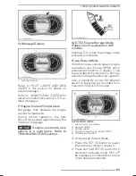
Page 60: ... flashing press the SET S button to select speedometer mode mmo2007 009 066_n 1 Speedometer mode Press the MODE M button to confirm selection or wait 5 seconds mmo2007 009 066_o B Tachometer RPM In addition of the analog type tachome ter RPM can also be displayed via the multifunction display Engine RPM can be displayed on dis play 1 or display 2 mmo2007 009 066_q MULTIFUNCTION DISPLAY 1 Display 1...

Page 61: ...s been reset Press the SET S button to select trip meter TRIP A TRIP B mode mmo2007 009 066_p 1 Trip meter TRIP A TRIP B mode Press and hold the SET S button to re set NOTE On E TEC models resetting TRIP B mode will also reset TOTAL FUEL CONSUMPTION mmo2007 009 066_k E Trip Hour Meter Records vehicle running time when the electrical system is activated since it has been reset Press the SET S butto...

Page 62: ...press the MODE M button to switch to minutes Use the SET S button to change minutes Press the MODE M button to save clock set up and exit mode G Fuel Level Bar gauge that continuously indicates the amount of fuel left in the fuel tank mmo2007 009 042_a FUEL LEVEL 1 Operating range H Altitude Displays vehicle approximate altitude above sea level calculated from the barometric pressure NOTE Altitude...

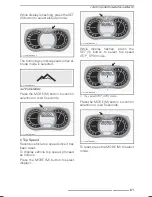
Page 63: ...it 5 seconds mmo2007 009 066_o I Top Speed Records vehicle top speed since it has been reset To display vehicle top speed proceed as follows Press the MODE M button to select display 1 mmo2007 009 066_m While display flashes press the SET S button to select top speed TOP_SPD mode mmo2007 009 066_n 1 Top speed TOP_SPD mode Press the MODE M button to confirm selection or wait 5 seconds mmo2007 009 0...

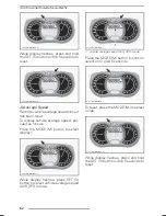
Page 64: ...ceed as follows Press the MODE M button to select display 1 mmo2007 009 066_m While display flashes press SET S button to select vehicle average speed AVR_SPD mode mmo2007 009 066_n 1 Vehicle average speed AVR_SPD mode Press the MODE M button to confirm selection or wait 5 seconds mmo2007 009 066_o To reset press the MODE M to select mode mmo2007 009 066_m While display flashes press and hold the ...

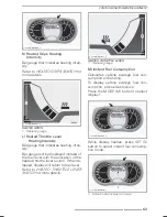
Page 65: ... activation of the heated throttle lever switch When re leased display will return to fuel level Refer to HEATED THROTTLE LEVER SWITCH for more details mmo2007 009 044_a HEATED THROTTLE LEVER 1 Operating range M Instant Fuel Consumption Calculates vehicle average fuel con sumption while riding To display vehicle average fuel con sumption proceed as follows Press the MODE M button to select display...

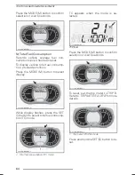
Page 66: ...ect display mmo2007 009 066_m While display flashes press the SET S button to select total fuel consump tion TC mode mmo2007 009 066_n 1 Total fuel consumption TC mode TC appears when the mode is se lected mmo2008 003 021_a TYPICAL Press the MODE M button to confirm selection or wait 5 seconds mmo2007 009 066_o To reset set the trip meter to TRIP B Refer to TRIP METER A OR B for more details mmo20...

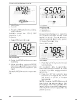
Page 67: ...is not available on ACE models Displays OIL when the storage mode procedure is initiated R Lap Record Mode With this mode vehicle speed engine revolutions per minute RPM and a preselected function in display 1 can be recorded at the same time during a period of time defined by the operator Also a possibility of nine 9 different sessions laps can be recorded for a maximum total of 2 5 minutes mmo20...

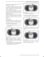
Page 68: ... record another session press the SET S button until REC record mode appears in display Repeat same pro cedure previously described to record To Review Recorded Data Select PLAY mode mmo2008 007 005_a PLAY MODE 1 Press the MODE M button to play recorded data All recorded data speedometer tachometer and the preselected mode in display 1 will be displayed at the same time 2 Press the SET S button to...

Page 69: ...PM Records engine top revolution per minute RPM since it has been reset To display engine top revolution per minute proceed as follows 1 Press the MODE M button to se lect display mmo2007 009 066_m NOTE Display will flash for approxi mately 5 seconds then will return to the previously selected mode if display is not changed 2 While display flashes press the SET S button to scroll and select top RP...

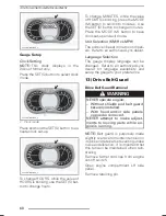
Page 70: ...can be set in metric or imperi als Refer to an authorized Lynx dealer Language Selection The gauge display language can be changed Refer to an authorized Lynx dealer for language availability and setup the gauge to your preference 13 Drive Belt Guard Drive Belt Guard Removal WARNING NEVER operate engine Without shields and belt guard securely installed With hood and or side panels opened or remove...

Page 71: ...e Insert the tab into the slot and push it into place mmo2013 004 024_a TYPICAL 1 Tab Position the grommet over the retain ing rod It may be necessary to slightly lift the console to make room mmo2009 003 011_a TYPICAL 1 Retaining rod Position rear portion of the belt guard over the retainer and secure it using the retaining pin NOTE Make sure rear portion of the belt guard is properly positioned ...

Page 72: ...ay mmo2007 009 043_b HEATING INTENSITY DISPLAY 1 Less heat 2 More heat Heated grips will be in OFF position when there are no bars displayed on the gauge 15 Heated Throttle Lever Switch BoonDocker and Rave RE Only NOTE Heated throttle lever is en abled above 2000 engine RPM Depress switch as required to select heating intensity to keep your thumb at a comfortable temperature fmo2014 001 009_b VARI...

Page 73: ...rage compartment pull the tab mmo2013 004 017_a 1 Tab 2 Storage compartment 18 Rear Rack WARNING All objects in rear rack must be properly latched Do not carry any breakable objects Excessive weight in rack may reduce steering ability Rear Rack LinQ Rave Xtrim and Rave RE Models CAUTION Always readjust suspension according to the load The capacity of this rack is limited the MAXIMUM cargo load is ...

Page 74: ...Q side Always load the front LinQ at first if possible Overloading can cause damage to frame and speed is proportional to the load 19 Upper Body Module Hood Upper Body Module Removal 1 Remove the gauge mbl2012 008 001_a Step 1 Unlock Step 2 Tilt 2 Disconnect the gauge connector 3 Disconnect the headlights connec tor fmo2014 002 032_a 1 Gauge connector 2 Headlights connector 4 Remove LH and RH side...

Page 75: ...ose at the ECM mbl2012 008 004_a 1 ECM 2 APS hose ACE Models 9 Pull backward the air intake tube fmo2014 002 034_a 1 Air intake tube 10 Remove the six upper body mod ule retaining screws three on each side fmo2014 002 005_a RH SIDE SHOWN 1 Retaining screws 11 Tilt the upper body module 5 de grees up towards the top section and then push it towards the front of the vehicle 12 Remove the upper body ...

Page 76: ... 2 Upper bottom pan opening 2 Slide the module towards rear fmo2014 002 008_b TYPICAL SLIDE TOWARDS REAR 3 On both sides install the upper body module retaining screws fmo2014 002 005_a RH SIDE SHOWN 1 Retaining screws 4 Connect APS hose on the ECM E tec Models Headlights connector Gauge connector Air temperature sensor ATS E tec Models Air intake connector tube 5 Install Gauge Drive belt guard 74...

Page 77: ...s fmo2014 001 006_a TYPICAL 1 Buttons To close a side panel set firmly on the stud location and push side panel locks to make sure it is secured Make sure lower front edge of the side panel goes to its right place and side panel is align fmo2014 002 023_a To remove a side panel open it then lift it up Free the lower hinge from its slot then free the upper hinge by lowering the panel To install a s...

Page 78: ...compartment CAUTION Do not use a higher rated fuse as this can cause severe damage to electrical components and or be a potential fire WARNING If fuse has burnt out source of mal function should be determined and corrected before restarting See an authorized Lynx dealer for servicing 23 Seat Latch Located under the seat fmo2014 001 011_a 1 Seat Latch Seat Removal Remove the storage battery compart...

Page 79: ...g the storage battery compartment cover NOTICE Install the seat first then push back the storage battery com partment cover to lock the seat prop erly in position fsi2013 010 003_a NOTE Ensure that the seat is secured properly fmo2015 001 022_b 24 Storage Battery Compartment NOTICE MAXIMUM load is 1 8 kg 4 lb evenly distributed Turn quarter turn fastener counter clockwise to release it and open co...

Page 80: ...r legs force Do not attempt to lift the rear of vehi cle if it is above your limits Use appropriate lifting device or have assistance to share lifting stress if possible WARNING Do not attempt to lift the vehicle by hand alone Use appropriate lifting device or have assistance to share lifting stress in order to avoid risk of strain injuries fmo2014 002 010_a FRONT 1 Front bumper fmo2014 002 013_a ...

Page 81: ...Control LEDC Electronic Controlled Suspension ECS Rave RE The operator can adjust damping force by Electronic Damping Control LEDC Refer to REAR SUSPENSION ADJUST MENT in the TUNE YOUR RIDE sec tion Xtrim SC 900 ACE Models The operator can adjust the comfort and ride height by Electronic Con trolled Suspension ECS Refer to REAR SUSPENSION ADJUST MENT in the TUNE YOUR RIDE sec tion 29 Ice Scratcher...

Page 82: ... with the hitch hook 3 Push the accessory attachment passed the safety tab 4 Secure safety tab using the hairpin clip Detaching an Equipment 1 Remove the hairpin clip 2 Push safety tab forward to free ac cessory attachment fromthe hitch 3 Detach accessory attachment 4 Install hairpin clip Hitch Tongue Type To attach an equipment to the hitch se cure the accessory tow bar to the hitch tongue using ...

Page 83: ... un til the reverse alarm sounds and the pilot lamp comes on in the analog digital gauge before oper ating throttle The reverse speed is not limited Always proceed with caution as fast reverse could result in loss of vehicle stability Come to complete stop before depress ing engaging the reverse Always remain seated and apply the brake before shifting Ensure the path behind is clear of obstacles o...

Page 84: ...ng MA XIMUM 10 ethanol The gasoline must have the following minimum oc tane requirements FUEL TYPE ENGINE MINIMUM OCTANE RATING Fuel which may contain up to 10 MAX ethanol All engines 95 E10 NOTICE Never experiment with other fuels Engine or fuel system damages may occur with the use of an inadequate fuel WARNING Always stop the engine before re fueling Fuel is flammable and ex plosive under certa...

Page 85: ...the fuel reservoir cap counterclockwise to remove it fmo2015 001 020_a TYPICAL 1 Fuel tank cap WARNING If a differential pressure condition is noticed whistling sound heard when loosening fuel reservoir cap have vehicle inspected and or re paired before further operation 4 Insert the spout into the filler neck 5 Pour fuel slowly so that air can es cape from the tank and prevent fuel flow back Be c...

Page 86: ...voir is located behind the RH side panel See BODY in MAINTENANCE PROCEDURES for opening procedure Always maintain a sufficient amount of recommended injection oil in the injec tion oil reservoir NOTICE Check level and refill ev ery time you refuel mmo2010 004 011_a 1 Oil reservoir 2 3 4 level 3 1 2 level 4 1 4 level To Add Injection Oil Remove injection oil reservoir cap Add injection oil NOTE Do ...

Page 87: ... some engine parameters The duration is based on fuel volume It will take approximately two fuel tanks to complete the break in During this period The engine performance and behav ior will not be optimal The fuel and oil consumption will be higher Drive Belt A new drive belt requires a break in pe riod of 50 km Avoid strong accelera tion deceleration pulling a load or high speed cruising During th...

Page 88: ...elerations than Standard or ECO mode Once activated Sport mode will re main active until it is deactivated by the operator Navigating Operating Modes Use ECO Standard Sport Mode switch to navigate between power levels from ECO reduced power to Stan dard full power to Sport increased response To increase power press the switch upwards To decrease power press the switch downwards fmo2014 002 012_a T...

Page 89: ...ting There are 3 levels available for the learning key mode Changing Learning Key Settings To change learning key setting carry out the following 1 Press the START electronic reverse button to wake up the electrical sys tem and install the NORMAL key on the engine cut off switch 2 Wait for the information center to complete its self test and display the key recognition message Analog Digital Gauge...

Page 90: ...available torque for learning key 6 After a few seconds the setting is automatically confirmed and saved NOTE The key speed setting is appli cable to any key of the same type used on a specific snowmobile The same key type used on a different snowmo bile may therefore have a different key speed setting NOTE Vehicle performance may vary depending on riding conditions 88 ______________ ...

Page 91: ...ing elec tric starter when engine has started could damage electric starter mech anism NOTE If for any reason the engine cannot be cranked electrically start en gine manually using the rewind starter 7 Release parking brake NOTE For an initial cold start do not release parking brake Perform the VEHICLE WARM UP procedure as ex plained below Vehicle Warm Up Before every ride vehicle has to be warmed...

Page 92: ... its normal operating tem perature before shifting Shifting in Reverse 1 Bring vehicle to a complete stop 2 Apply and hold brake Remain seated refer to RIDER POSITION REVERSE OPERATION for pos ture information 3 With engine at idle speed press and release the RER button 4 Wait until reverse beeper sounds then gently depress throttle lever WARNING Engaging the reverse mode is done by depressing the...

Page 93: ...ss throttle lever Shifting in Forward To engage forward gear proceed as follows 1 Bring vehicle to a complete stop 2 Apply and hold brake 3 With engine at idle speed push the reverse shift lever all the way in 4 Gently depress throttle lever Shutting Off the Engine Release throttle lever and wait until en gine has returned to idle speed Shut off the engine using either en gine cut out switch or te...

Page 94: ...cause serious dam age to the snowmobile Temperature The engine management of these en gines provides the optimum air fuel ra tio for all temperatures Hard Packed Snow Models Equipped with Minimum Track Profile of 1 75 in BRP does not recommend to ride a snowmobile equipped with high lug profile track at high speed in a trail on hard packed surfaces or ice for an ex tended period of time In the eve...

Page 95: ... by the han dle only Do not start the snowmo bile by the drive pulley unless it is a true emergency situation Have the snowmobile repaired as soon as possible mmo2008 005 008_a Attach one end of emergency rope to rewind handle NOTE The spark plug socket can be used as an emergency handle mmo2008 005 007 Attach the other end of emergency rope to the starter clip supplied in the tool kit mmo2008 005...

Page 96: ... tow bar is not available a rope can be used provided you proceed with extra caution In some areas it may be ille gal to do so Check with state or local authorities Remove the drive belt attach the rope to the ski legs spindles have some one sit on the towed snowmobile to ac tivate the brake and tow at low speed CAUTION In order to prevent damage to the steering system never attach the tow rope to...

Page 97: ...L OPERATING INSTRUCTIONS WARNING Do not tow the vehicle facing back wards If the vehicle is towed facing backwards the wind may cause damage to the windshield or even loss of the windshield _______________ 95 ...

Page 98: ...ting suspension Support rear of vehicle off the ground with a wide base snow mobile stand with a rear deflec tor panel Make sure support device is sta ble and secure The best way to set up the suspen sion is to customize each adjustment one at a time Various adjustments are interrelated It may be necessary to readjust center spring after adjust ing front springs for instance Test run the snowmobil...

Page 99: ...nts as well as snow conditions will dictate the most effi cient combination Generally a longer stopper strap set ting gives better performance in deep snow on a flat landscape and a shorter setting will improve handling in steep hill climbing conditions Center Spring Center spring preload has an effect on steering effort handling and bump ab sorption Also since center spring preload ad justment pu...

Page 100: ...eering effort and handling Slight suspension bottoming occurring under the worst riding conditions indi cates a good choice of spring preload ACTION RESULT Firmer rear suspension Higher rear end More bump absorption capability Heavier steering Increasing preload Rear suspension Better sidehilling on deep snow Softer rear suspension Lower rear end Less bump absorption capability Lighter steering Be...

Page 101: ...ng the left knob till the led lights up in right position Push the right knob to set the damping Upwards is more damping and down is less damping fmo2015 001 003_a 1 SKI Skies shocks 2 CB Center shock 3 RB Rear shock A Left knob B Right knob In the LEDC system it is also possible to adjust the shape of damping curve by mechanical adjusters In all shocks there are own adjusters for the low speed LS...

Page 102: ...h the left knob till the MAN shock figure led lights up Push the right knob to set the damping Upwards is more damping and down is less damping Spring Preload Adjuster MAN manual The spring preload is fundamental for the function of the suspension If the preload is incorrectly set any other adjustments will not help to get the in tended performance from the suspen sion More spring preload is neede...

Page 103: ...epa retely Low speed compression damping con trols how the shock absorber reacts to a low suspension velocity slow com pression strokes in most cases when riding at lower speeds High speed compression damping controls how the shock absorber re acts to a high suspension velocity quick compression strokes in most cases when riding at higher speeds ACTION RESULT ON BIG AND SMALL BUMPS Increasing comp...

Page 104: ...i leg skis are set to the narrower stance fmo2014 003 009_a 1 Spacer on inside of ski leg When the spacer is installed outside the ski leg skis are set to the wider stance To change the ski stance proceed as follows on both sides 1 Lift the front of vehicle 2 Remove the ski bolt 3 Place the spacer according to the desired stance see illustration fbg2013 009 002_b PARTS LAYOUT RH SIDE SHOWN 1 Ski l...

Page 105: ... an effect on front suspension firmness Front ski spring preload also has an ef fect on the steering behavior NOTICE In order to have a suffi cient preload the spring free length with skis off the ground must not exceed 270 mm 10 63 in An in sufficient preload can cause the spring stopper to fall off the shock absorber mmo2010 003 020_e TYPICAL A Maximum 270 mm 10 63 in with skis off the ground AC...

Page 106: ... 36 R SHOWN 1 Adjustment ring 2 Ring positions fmo2012 003 039_a KYB 40 PB HLCR SHOWN 1 Adjustment ring mmo2010 003 027_a CAM TYPE HPG SHOCK ABSORBER 1 Decrease preload 2 Increase preload 3 Spring preload adjustment cam mmo2010 003 019_a TYPICAL RING TYPE 1 Spring preload adjustment ring 2 Increase preload 3 Decrease preload 104 ______________ ...

Page 107: ...compression damping force Softer compression damping To adjust turn clockwise to increase compression damping force and coun terclockwise to decrease compression damping force fmo2012 003 039_c 1 Compression damping adjuster knob Shock Rebound Damping KYB 40 PB HLCR Rebound damping controls how the shock absorber restrains the exten sion stroke Turn the damping adjuster accordingly Turning it cloc...

Page 108: ... cornering or acceleration Shorten limiter strap Increase rear spring preload Rear of snowmobile seems too stiff Reduce rear spring preload Reduce compression damping adjustment if equipped Rear of snowmobile seems too soft Increase rear spring preload Rear suspension is frequently bottoming Increase rear spring preload Increase center spring preload Lengthen limiter strap Increase compression dam...

Page 109: ... Cam position 4 Rave RE 8 mm 5 mm 10 mm Rave RE with LEDC 10 mm 5 mm 12mm Xtrim SC 11 mm 8 mm 7 mm Xtrim SC with ECS2 11 mm 8 mm 5 mm Boondocker 3700 3900 4 mm Cam position 1 4 mm Cam position 1 5 mm Cam position 1 800 HO E TEC Models Rave RE 8 mm 5 mm 10 mm Rave RE with LEDC 10 mm 5 mm 12 mm Boondocker STD 3700 4 mm Cam position 1 4 mm Cam position 1 5 mm Cam position 1 Boondocker RE 3700 10 mm 5...

Page 110: ...pen High Speed 1 5 Turns open Boondocker RE 3700 800 E TEC Xtirm RE 3500 800 E TEC Rebound 10 Clicks open Rebound 3 Clicks open Rebound 3 Clicks open COMFORT SETUPS MODEL SKI SHOCK CENTER SHOCK REAR SHOCK 505074001 505074002 503194402 503194404 Low Speed 20 Clicks open Low Speed 20 Clicks open Low Speed 20 Clicks open High Speed 2 5 Turns open High Speed 2 0 Turns open High Speed 2 0 Turns open Ra...

Page 111: ...MAINTENANCE INFORMATION ______________ 109 ...

Page 112: ...k for leaks Tighten exhaust manifold screws to specified torque ENGINE Check coolant level Inspect fuel lines and connections FUEL SYSTEM Inspect throttle cable Inspect drive belt Visually inspect drive pulley Tighten drive pulley retaining screw to specified torque Inspect driven pulley Adjust and align track Change chaincase gearbox oil Adjust drive chain except models with gearbox Check brake f...

Page 113: ... Inspect exhaust system and check for leaks ENGINE Check coolant level FUEL SYSTEM Inspect fuel lines and connections Inspect drive belt Visually inspect drive pulley Tighten drive pulley retaining screw to specified torque Inspect driven pulley Check driven pulley preload Adjust and align track Change chaincase gearbox oil Adjust drive chain Not for models equipped with gearbox Check brake fluid ...

Page 114: ...t suspension Inspect rear suspension including stopper straps and slider shoes SUSPENSION Retighten PPS2 rear axle bolt 1 4 turn BODY Adjust seat lock plate only REX2 models FIRST INSPECTION 4 STROKE AFTER THE FIRST 3 000 KM 2 000 MI OR 1 YEAR OF OPERATION WHICHEVER COMES FIRST ENGINE Change engine oil and filter 112 ______________ ...

Page 115: ...s and check for leaks ENGINE Adjust engine stopper Visually inspect and clean drive pulley Tighten drive pulley retaining screw to specified torque Clean driven pulley Adjust and align track DRIVE SYSTEM AND BRAKE Inspect brake hose pads and disk STEERING SYSTEM Inspect steering mechanism FRAME Retigthen rear member screws to frame to specified torque REX2 35 N m 26 lbf ft Inspect front suspension...

Page 116: ... O rings and sliding sheave bushing E TEC SUSPENSION Check PPS2 bushing and bearing Replace both if either one is worn EVERY 10 000 KM 6 000 MI OR 3 YEARS WHICHEVER COMES FIRST E TEC Inspect oil pump strainer and clean if needed ENGINE Clean 3D rave valves DRIVE SYSTEM Replace the following drive pulley wear parts spring cover bushing and ramps E TEC ELECTRICAL SYSTEM E TEC Replace spark plugs EVE...

Page 117: ...r leaks ACE Visually inspect and clean drive pulley Tighten drive pulley retaining screw to specified torque Check driven pulley preload Clean driven pulley Adjust and align track DRIVE SYSTEM AND BRAKE Inspect brake hose pads and disk STEERING SYSTEM Inspect steering mechanism FRAME Retigthen rear member screws to frame to specified torque REX2 35 N m 26 lbf ft Inspect front suspension Inspect re...

Page 118: ...filter FUEL SYSTEM Replace fuel pump outlet filter ACE Replace drive pulley slider shoes O ring and rollers and inspect ramps 900 ACE DRIVE SYSTEM AND BRAKE Replace brake fluid SUSPENSION Check PPS2 bushing and bearing Replace if needed EVERY 10 000 KM 6 000 MI OR 3 YEARS WHICHEVER COMES FIRST ELECTRICAL SYSTEM Replace spark plugs EVERY 5 YEARS ENGINE Replace engine coolant 116 ______________ ...

Page 119: ...n good condi tion fmo2014 001 021_a 1 RH Air filter If the air filter has to be cleaned or re placed see an authorized Lynx dealer repair shop or person of your own choosing Engine Coolant WARNING Never open coolant tank cap when engine is hot Engine Coolant level Verification Check coolant level at room tempera ture Liquid should be at cold level line engine cold of coolant tank NOTE When checkin...

Page 120: ...nt Damages caused by oil which is not suitable for this 4 stroke engine may not be covered by the BRP limited warranty If the recommended oil is not avail able use SAE 0W 40 synthetic based oil that meets or exceeds the require ments for API service classification SM Engine Oil Level Verification NOTICE Check level every 10 hours of use and refill if necessary Do not overfill Operating the en gine...

Page 121: ...TROLS INSTRU MENTS EQUIPMENT section 4 Remove dipstick mmo2014 004 011_a LH SIDE OF VEHICLE 1 Oil tank dipstick 5 From underneath the vehicle ac cess the drain plug 5 1 Remove one access cover re taining screw and loosen the other 5 2 Pivot the access cover to clear the bottom pan opening fmo2014 002 015_a 1 Drain plugs access cover fmo2014 002 015_c PIVOT THE ACCESS COVER 1 Retaining screws 6 Fro...

Page 122: ...place OIL FILTER see proce dure in this subsection 13 Refill oil tank at the proper level with the recommended oil APPROXIMATE ENGINE OIL CAPACITY WITH FILTER 600 ACE 2 1 L 2 2 qt U S liq APPROXIMATE ENGINE OIL CAPACITY WITH FILTER 900 ACE 3 3 L 3 5 qt U S liq 14 Reinstall dipstick in oil tank and properly tighten it 15 Start engine and let it idle for a few minutes 16 Ensure there are no leaks 17...

Page 123: ... 5 Tighten oil filter cover screws to the specified torque TIGHTENING TORQUE Oil filter cover screws 10 N m 2 N m 89 lbf in 18 lbf in Exhaust System The muffler tail pipe should be cen tered with the exit hole in the bottom pan Exhaust system must be free of rust or leaks Make sure that gear clamps are properly tightened Check retaining springs condition and replace if necessary The exhaust system...

Page 124: ...nt may be performed by an authorized Lynx dealer repair shop or person of your own choosing Spark plugs in spection or replacement requires an in depth technical knowledge Though not required it is recommended that an authorized Lynx dealer performs spark plugs inspection or replacement Engine Stopper E TEC Engine Stopper Adjustment The engine stopper is located on the LH front engine support in f...

Page 125: ...TICE Serious pulley damage can occur if the engine stopper and its screws are not properly installed Brake Fluid Recommended Brake Fluid Use only DOT 4 brake fluid from a sealed container An opened container may be contaminated or may have ab sorbed moisture from the air WARNING Use only DOT 4 brake fluid from a sealed container To avoid serious damage to the braking system do not use fluids other...

Page 126: ...rify the condi tion wear of the brake pads Brake Adjustment No adjustment is provided for hydraulic brake See an authorized Lynx dealer if any problems Chaincase Oil Recommended Chaincase Oil RECOMMENDED CHAINCASE OIL P N 619 590 098 NOTICE The chaincase of this snowmobile has been developed and validated using the XPS Syn thetic chaincase oil BRP strongly recommends the use of its XPS Synthetic c...

Page 127: ...rocedure Remove the magnetic check plug Remove the filler cap on the chaincase cover E TEC Models mmo2009 003 009_a 1 Filler cap ACE Models mmo2011 003 017_a TYPICAL 1 Check plug mbs2010 019 001_a 1 Filler cap All Models Pour recommended oil in chaincase by the filler hole until oil comes out by the check plug hole Reinstall check plug and torque to specification TIGHTENING TORQUE Check plug 6 N m...

Page 128: ...e Belt Drive Belt Inspection Inspect belt for cracks fraying or ab normal wear uneven wear wear on one side missing cogs cracked fab ric If abnormal wear is noted prob able cause could be pulley misalign ment excessive RPM with frozen track fast starts without warm up pe riod burred or rusty sheave oil on belt or distorted spare belt Contact an au thorized Lynx dealer Drive Belt Replacement Drive ...

Page 129: ...IVE BELT GUARD INSTALLATION section in CONTROLS INSTRU MENTS EQUIPMENT 7 Close side panel refer to HOOD AND SIDE PANELSsection in CON TROLS INSTRUMENTS EQUIP MENT Drive Belt Height Adjustment The drive belt height must be checked every time a new belt is installed To adjust the drive belt height proceed as follows 1 Remove D E S S key frompost 2 Open LH side panel refer to HOOD AND SIDE PANELS sec...

Page 130: ... is too tight If the vehicle creeps lower the drive belt height from the preliminary set ting Repeat procedure until creeping stops Reverse Activation NOTE The reverse may not activate if the belt is positioned too high in the driven pulley If reverse activation does not work properly ensure the drive belt is properly adjusted Adjust the drive belt lower in the driven pulley if needed Drive Pulley...

Page 131: ...0 RPM and higher position numbers increase it in steps of 200 RPM Example Calibration screws initially set at posi tion 4 and changed to position 6 will increase maximum engine RPM by 400 RPM Procedure Loosen the lock nut just enough to get the calibration screw head out of the pulley and rotate to the desired posi tion Do not completely remove the lock nut Set all 3 calibration screws to the same...

Page 132: ...ard packed surfaces or ice for an ex tended period of time In the event that you have to reduce your speed then minimize the dis tance you ride on those surfaces CAUTION Running those tracks at high speed in a trail on hard packed surfaces or ice put more stress on the lugs which tend to heat up as a result To avoid poten tial degradation or damage to the track reduce your speed then mini mize the...

Page 133: ...rior to adjust ing track tension Remove the tether cord cap DESS key Lift rear of snowmobile and support it with a wide base snowmobile me chanical stand CAUTION Use proper lifting techniques notably using your legs force Do not attempt to lift the rear of vehicle if it is above your limits Allow the suspension to extend nor mally and check gap halfway between front and rear idler wheels Measure b...

Page 134: ...of the track Never rotate track at high speed Centrifugal force could cause de bris pieces of torn track or an en tire severed track to be violently thrown backwards out of the tun nel with tremendous force possi bly resulting in the loss of a leg or other serious injury WARNING Remove the tether cord cap DESS key before performing any main tenance or adjustment unless oth erwise specified Vehicle...

Page 135: ...aining screw TIGHTENING TORQUE Wheel retaining screws 48 N m 6 N m 35 lbf ft 4 lbf ft 6 Restart engine and rotate track slowly to recheck alignment 7 Reposition snowmobile on the ground 8 Install rear wheel caps if so equipped Suspension Rear Suspension Condition Visually inspect all suspension compo nents including slider shoes springs wheels etc NOTE During normal driving snow will act as a lubr...

Page 136: ...INGS REAR fmo2015 001 041_b TYPICAL PPS2 3700 AND 3900 GREASE FITTINGS FRONT fmo2015 001 040_b TYPICAL PPS2 3700 AND 3900 GREASE FITTINGS REAR Steering and Front Suspension Condition Visually inspect steering and front sus pension for tightness of components steering arms control arms and links tie rods ball joints ski bolts ski legs etc If necessary contact an autho rized Lynx dealer Skis Wear an...

Page 137: ...e 2 Check if melted CAUTION Do not use a higher rated fuse as this can cause severe damage to electrical components and or be a potential fire WARNING If fuse has burnt out source of mal function should be determined and corrected before restarting See an authorized Lynx dealer for servicing E E TEC Manual Start mmo2008 008 028_a TYPICAL RH SIDE OF ENGINE COMPARTMENT 1 5 A main fuse E TEC Electric...

Page 138: ...ghts Bulb Replacement NOTICE Never touch glass portion of an halogen bulb with bare fingers it shortens its operating life If glass is touched clean it with isopropyl al cohol which will not leave a film on the bulb 1 Open the front storage compart ment by pulling the tab mmo2013 004 017_a 1 Tab 2 Storage compartment 2 Remove the applicable rubber boot mmo2013 004 020_a 1 Rubber boots NOTE Make su...

Page 139: ...nd replace Properly rein stall parts Headlights Beam Aiming Open the front storage compartment Turn knob to adjust beam height Turn knob clockwise to lower the beam height Turn knob counterclockwise to raise the beam height mmo2013 004 020_b TYPICAL 1 Knob Taillight Led taillight leds cannot be replaced If failed change taillight assy Fasten new taillight by screws Ice Scratchers BoonDocker Ice Sc...

Page 140: ... scratches on windshield or hood use the Scratch Remover Kit P N 861 774 800 CAUTION Never clean plastic parts or hood with strong detergent degreasing agent paint thinner ace tone products containing chlorine etc Wax painted portion of the vehicle for better protection NOTE Apply wax on glossy finish only Protect the vehicle with a cover to prevent dust accumulation during storage Clean sheaves o...

Page 141: ... stress If a lifting de vice is not used use proper lifting techniques notably using your legs force Do not attempt to lift the rear of vehicle if it is above your limits NOTICE The snowmobile has to be stored in a cool and dry place and covered with an opaque but ven tilated tarpaulin This will prevent sun rays and grime from affecting plastic components and vehicle fin ish NOTICE Fuel stabilizer...

Page 142: ...HI LOW beam switch rapidly then while doing this press and hold the SET button until PUSH S appears on the display NOTE It is critical for this procedure to depress the HI LOW beam switch repeatedly before holding down the SET button mmr2009 004 003 5 Release all buttons when gauge dis plays PUSH S appears 6 Again press and hold the SET S button 2 3 seconds NOTE The gauge will display OIL when the...

Page 143: ...just at every drive belt replacement Clean and visually inspect drive pulley Clean and inspect driven pulley Inspect adjust and align track Adjust drive chain Not for models equipped with gearbox Change chaincase gearbox oil Check brake fluid level DRIVE SYSTEM AND BRAKE Inspect brake hose pads and disk Inspect steering mechanism STEERING SYSTEM Inspect skis and runners Inspect front suspension SU...

Page 144: ...n and visually inspect drive pulley Clean and inspect driven pulley Inspect adjust and align track Adjust drive chain Not for models equipped with gearbox Change chaincase gearbox oil Check brake fluid level DRIVE SYSTEM AND BRAKE Inspect brake hose pads and disk Inspect steering mechanism STEERING SYSTEM Inspect skis and runners Inspect front suspension SUSPENSION Inspect rear suspension and stop...

Page 145: ...TECHNICAL INFORMATION ______________ 143 ...

Page 146: ...zed Lynx dealer to complete warranty claims properly We strongly recommend that you take note of all the serial numbers on your snowmobile and supply them to your insurance company Vehicle Identification Number VIN VIN is scribed on the vehicle descrip tion decal See above It is also en graved on the tunnel near the vehicle description decal Model number and model year are part of the information ...

Page 147: ...VEHICLE IDENTIFICATION mmo2011 003 003_a 600 ACE ENGINE 1 Engine identification number mmo2014 004 007_a 900 ACE ENGINE 1 Engine identification number ______________ 145 ...

Page 148: ...ty Kwa 3 dB Noise Sound pressure LpA 86 dB 4050 RPM Uncertainty KpA 3 dB 89 dB 3950 RPM Uncertainty KpA 3 dB 80 dB 3625 RPM Uncertainty KpA 3 dB 80 dB 3625 RPM RPM Uncertainty KpA 3 dB Hand arm system 2 5m s2 4050 RPM 2 5m s2 3950 RPM 2 5 m s2 3625 RPM 2 5m s2 3625 RPM Vibration Whole body at seat 0 5m s2 4050 RPM 0 5m s2 3950 RPM 0 5 m s2 3625 RPM 0 5m s2 3625 RPM 1 Noise emission and Vibration v...

Page 149: ...ddd2009 001 The EC Declaration of Conformity does not appear in this version of the Operator s Guide Please refer to the printed version that was delivered with your vehicle EN ...

Page 150: ...ible for compliance could void the user s authority to operate the equip ment IC Registration Number 12006A M01456 FCC ID 2ACERM01456 We the party responsible for compli ance declare under our sole respon sibility that the device is in confor mity with the provisions of the follow ing Council Directive 2014 53 EU To which this declaration relates is in conformity with the essential re quirements a...

Page 151: ... 100 RPM Fuel injection system E TEC Direct injection Exhaust system Single tuned pipe baffle muffler Engine oil Refer to RECOMMENDED OIL section 1 Engine oil tank capacity 3 7 L 3 9 qt U S liq Coolant Ethyl glycol water mix 50 coolant 50 distilled water Use LONG LIFE ANTIFREEZE F P N 619 590 204 or coolant specifically designed for aluminum engines Recommended fuel Premium unleaded fuel which may...

Page 152: ...nominal width All others 40 6 cm 15 984 in Rave Rave RE 326 9 cm 128 701 in Xtrim RE 3500 Series 348 7 cm 137 28 in Xtrim SC Boondocker 3700 Series 370 5 cm 146 in Track nominal length Boondocker 3900 Series 392 3 cm 154 449 in Rave 35 mm 1 378 in Rave RE 35 mm 1 378 in 41 mm 1 61 in Xtrim RE 3500 44 mm 1 73 in Xtrim SC 39 mm 1 535 in Track profile height Boondocker Series 64 mm 2 52 in Rave Rave ...

Page 153: ...b Track alignment Equal distance between edges of track guides and slider shoes BRAKE SYSTEM Brake system type Hydraulic RE X brake type Brake fluid DOT 4 SUSPENSION Front suspension All Models A LFS Rave HPG 36 Rave RE Xtrim RE 3500 KYB 40 HLCR Rave RE LEDC Tractive 46 HCL EDC Xtrim SC KYB 36 R Front shock BoonDocker 3700 3900 HPG 36 Rave Rave RE Xtrim RE 3500 242 mm 9 528 in Front suspension max...

Page 154: ...r suspension max travel All 390 mm 15 354 in ELECTRICAL SYSTEM Lightning system output 12V 55V 1340W Headlights bulb HI LOW beam 2 x 60 55 Watts H 4 Taillight bulb Led Type NGK PZFR6F 3 Spark plug Gap Not adjustable 0 8 0 0 1mm 0 75 mm 0 05 mm 03 in 002 in not adjustable Fuse Refer to FUSES in MAINTENANCE DIMENSIONS AND WEIGHT Rave Rave RE 301 5 cm 118 701 in Xtrim RE 3500 310 cm 122 in Xtrim SC 3...

Page 155: ...tric start LEDC 228 kg 502 7 lb Rave RE RS Rave RE 41mm track profile 220 kg 485 lb Rave RE electric start RS Rave RE electric start 41mm track profile Xtrim SC 232 kg 511 5 lb Rave RE RS 41mm track profile 222 kg 489 4 lb Rave RE RS electric start 41mm track profile 230 kg 507 1 lb Xtrim RE 3500 225 kg 496 lb Xtrim RE 3500 electric start 235 kg 518 1 lb Xtrim SC ECS2 BoonDocker 3700 electric star...

Page 156: ...onDocker std 3700 Boondocker std 3900 BoonDocker 3900 921 mm 21 mm 36 26 in 827 in Ski width All 188 mm 7 402 in 1 Refer to INJECTION OIL subsection for detailed information 2 Measure gap between slider shoe and bottom inside track when exerting a downward pull to the track 3 NOTICE Do not attempt to adjust gap on this spark plug 154 ______________ ...

Page 157: ...ine oil tank capacity 3 7 L 3 9 qt U S liq Mixture Ethyl glycol water mix 50 coolant 50 distilled water Coolant Premix Use LONG LIFE ANTIFREEZE F P N 619 590 204 or coolant specifically designed for aluminum engines Recommended fuel Premium unleaded fuel which may contain up to 10 MAX ethanol Regular unleaded Minimum octane rating Refer to FUEL REQUIREMENTS 95 E RON E10 Fuel tank capacity 34 L 8 9...

Page 158: ... 49 Drive sprocket number of teeth 7 Rave RE 38 cm 14 961 in Track nominal width All others 40 6 cm 16 in Rave RE 326 9 cm 10 725 ft Xtrim RE 3500 348 7 cm 137 283 in Boondocker 3700 Series 370 5 cm 145 866 in Boondocker 3900 Series 392 3 cm 154 449 in Track nominal length Boondocker DS 4100 414 1 cm 163 031 in Rave RE 35 mm 1 38 in 41 mm 1 61 in Xtrim RE 3500 44 mm 1 732 in 59 mm 2 32 in Boondock...

Page 159: ...0 kg 0 lb Boondocker Series Deflection 60 mm 70 mm 2 362 in 2 756 in Track tension Force 2 7 3 kg 16 lb Track alignment Equal distance between edges of track guides and slider shoes BRAKE SYSTEM Brake system type Brembo hydraulic caliper self adjustable disk Brake fluid DOT 4 SUSPENSION Front suspension All A LFS Rave RE KYB 40 HLCR Rave RE LEDC Tractive 46 HCL EDC Xtrim RE 3500 KYB 40 HLCR Boondo...

Page 160: ...ndocker DS 3900 KYB 36 Center shock Boondocker DS 4100 KYB 36 Rave RE KYB 46 PB HLCR Rave RE LEDC Tractive 46 HCL EDC Xtrim RE 3500 KYB 46 PB HLCR Boondocker 3700 3900 HPG 36 Boondocker RE 3700 KYB 46 PB HLCR Boondocker DS 3900 KYB 46 Rear shock Boondocker DS 4100 KYB 46 Rear suspension max travel All 390 mm 15 354 in ELECTRICAL SYSTEM Lightning system output 12V 55V 1340 W Headlights bulb HI LOW ...

Page 161: ...E 3500 120 cm 47 244 in Vehicle overall height Boondocker Series 128 cm 50 394 in Rave RE Boondocker 3900 Boondocker DS 3900 225 kg 496 lb Rave RE RS electric start Rave RE 41mm track profile electric start 237 kg 522 5 lb Rave RE RS 41mm track profile electric start Boondocker DS 3900 AR electric start 239 kg 526 9 lb Rave RE LEDC Xtrim RE 3500 59mm track profile 236 kg 520 3 lb Xtrim RE 3500 232...

Page 162: ...ondocker DS 4100 electric start Boondocker DS AR 4100 electric start 238 kg 524 7 lb Rave RE RS Rave RE 41mm track profile 227 kg 500 4 lb Dry weight cont d Rave RE RS 41mm track profile 229 kg 504 9 lb Rave RE 1 080 mm 42 52 in Xtrim RE 3500 996 mm 21 mm 39 213 in 827 in Boondocker RE 3700 996 mm 21 mm 39 213 in 827 in Ski stance All others 921 mm 21 mm 36 26 in 827 in Ski width All 188 mm 7 402 ...

Page 163: ...lycol water mix 50 coolant 50 distilled water Use BRP LONG LIFE ANTIFREEZE F P N 619 590 204 or coolant specifically designed for aluminum engines FUEL SYSTEM Fuel injection system Multi point EFI 46 mm throttle body Recommended fuel Regular unleaded fuel containing MAXIMUM 10 ethanol Minimum octane rating RON 95 E10 fuel which may contain up to 10 MAX ethanol Fuel tank capacity 34 L 8 98 U S gal ...

Page 164: ... and relays R3 Fuse 2 F5 ignition coils fuel injectors DRIVE SYSTEM Drive pulley type eDrive II LC Driven pulley type QRS short shaft Engagement 2200 RPM Type P N 619 590 098 Chaincase oil Capacity 500 ml 16 9 U S oz Drive Belt Part Number Rave Xtrim 417 300 127 1 Small sprocket number of teeth Rave Xtrim 21 Large sprocket number of teeth Rave Xtrim 51 Drive sprocket number of teeth Rave Xtrim 8 1...

Page 165: ...orce 0 kg 0 lb Rave 40 mm 50 mm 1 575 in 1 969 in Deflection Xtrim 50 mm 60 mm 1 969 in 2 362 in Track tension Force 1 7 3 kg 16 lb Track alignment Equal distance between edges of track guides and slider shoes BRAKE SYSTEM Brake system type Hydraulic REX brake type Brake fluid DOT 4 SUSPENSION Front suspension A LFS Front shock Rave Xtrim HPG 36 Rave 242 mm 9 528 in Front suspension max travel Xtr...

Page 166: ...overall length Xtrim 317 cm 124 8 in Rave 126 5 cm 49 8 in Vehicle overall width Xtrim 118 cm 46 46 in Rave 121 cm 47 638 in Vehicle overall height Xtrim 132 cm 51 97 in Rave 1 080 mm 42 52 in Ski stance Xtrim 996 mm 21 mm 39 213 in 827 in 1 Drive belt height must be adjusted every time a new drive belt is installed Confirm drive belt part number application with an authorized Lynx dealer 164 ____...

Page 167: ...ater mix 50 coolant 50 distilled water Use BRP LONG LIFE ANTIFREEZE F P N 619 590 204 or coolant specifically designed for aluminum engines FUEL SYSTEM Fuel injection system Multi point EFI 46 mm throttle body Recommended fuel Regular unleaded fuel containing MAXIMUM 10 ethanol Minimum octane rating Refer to FUEL REQUIREMENTS 95 RON fuel which may contain up to 10 MAX ethanol Fuel tank capacity 34...

Page 168: ...eDrive II Driven pulley type QRS short shaft Engagement 2200 RPM Type P N P N 619 590 098 Chaincase oil Capacity 500 ml 16 9 U S oz Drive Belt Part Number 417 300 383 1 Small sprocket number of teeth 24 Large sprocket number of teeth 49 Drive sprocket number of teeth 8 Track nominal width 40 6 cm 15 984 in Track nominal length 370 5 cm 145 866 in Track profile height 39 mm 1 535 in Deflection 35 m...

Page 169: ...hock Xtrim SC ESC2 Tractive 46HLC EDC PA Rear suspension max travel 390 mm 15 354 in WEIGHT AND DIMENSIONS Xtrim SC 251 kg 553 4 lb Dry weight Xtrim SC ESC2 252 kg 555 6 lb Vehicle overall length 327 cm 128 74 in Vehicle overall width 118 cm 46 46 in Vehicle overall height 132 cm 51 97 in Ski stance 996 mm 21 mm 39 213 in 827 in 1 Drive belt height must be adjusted every time a new drive belt is i...

Page 170: ...SPECIFICATIONS This page is intentionally blank 168 ______________ ...

Page 171: ...TROUBLESHOOTING ______________ 169 ...

Page 172: ...install tether cord cap 2 D E S S has read a different code than the one programmed D E S S pilot lamp blinks rapidly fast short beeps repetitive Install a tether cord cap for which this snowmobile was programmed 3 ECM does not recognize the D E S S key ACE Refer to an authorized Lynx dealer ENGINE LACKS ACCELERATION OR POWER 1 Learning key used ACE Use a Normal key 2 Sport mode not activated ACE ...

Page 173: ...authorized Lynx dealer repair shop or person of your own choosing for maintenance repair or replacement 3 Exhaust system leak Seek service from an authorized Lynx dealer repair shop or person of your own choosing for maintenance repair or replacement 4 Fuel pressure too low Seek service from an authorized Lynx dealer repair shop or person of your own choosing for maintenance repair or replacement ...

Page 174: ... ARE NOT WORKING 1 Engine RPM is too low Make sure engine RPM is above 2000 ACE ENGINE HAS SHUT DOWN 1 The engine shuts down after long periods of idling Do not let engine idle too long Refer to VEHICLE WARM UP in OPERATING INSTRUCTION 172 ______________ ...

Page 175: ... lamp On the multifunction analog digital gauge the display is used as a comple ment of the pilot lamps to give you a brief description if an anomaly occurs or to inform you of a particular condi tion mmo2007 009 066_c 1 Message display Messages will be displayed with a beep code and pilot lamp s Beeper codes will be heard and mes sages depending on gauge model will be displayed to catch your atte...

Page 176: ...e engine if condition persists 4 short beeps every 30 seconds MUFFLER Reduce speed or stop engine Let engine cool down and restart If overheating persists contact an authorized Lynx dealer Do not run the engine if condition persists ENGINE OVERHEAT Critical overheat Stop engine immediately and let engine cool down Check coolant level refer to MAINTENANCE If coolant level is correct and overheating...

Page 177: ...at maximum engine RPM is reached Check clutch calibration Short beeps repeating rapidly SHUTDOWN Shutdown procedure in force due to engine overheating or fuel pump problem remove tether cord cap from engine cut off switch and contact an authorized Lynx dealer COMMUNICATION Communication problem between ECM and gauge Stop engine remove tether cord cap Wait a few minutes then start engine If problem...

Page 178: ...hile attempting an engine start engine cranks but won t run Release throttle while starting Fault Codes M Multifunction Analog Digital Display Only To read any active fault code press and hold MODE M Button and simultaneously depress the HI LOW beam switch repeatedly several times If two or more codes are registered use SET S or MODE M to scroll To exit the fault codes mode press and hold MODE M b...

Page 179: ...WARRANTY ______________ 177 ...

Page 180: ... point during the warranty period it has commercial tags or is licensed for commercial use The repair or replacement of parts or the performance of service under this war ranty does not extend the life of this warranty beyond its original expiration date Note that the duration and any other modalities of the warranty coverage are sub ject to the applicable national or local legislation in the cust...

Page 181: ...s Guide Damage resulting from removal of parts improper repairs service mainte nance modifications or use of parts not manufactured or approved by BRP or resulting from repairs done by a person that is not an authorized servicing BRP distributor dealer Damage caused by abuse abnormal use neglect use of the product on sur faces other than snow or operation of the product in a manner inconsistent wi...

Page 182: ...is transferred during the warranty coverage period this limited warranty subject to its terms and conditions shall also be transferred and be valid for the remaining coverage period provided BRP or an authorised BRP distributor dealer receives a proof that the former owner agreed to the transfer of ownership in addition to the co ordinates of the new owner 9 CONSUMER ASSISTANCE In the event of a c...

Page 183: ... Signature Print Hours Date Dealer no Notes For maintenance schedule refer to Maintenance Information section of this operator s guide SERVICE Mileage km Signature Print Hours Date Dealer no Notes For maintenance schedule refer to Maintenance Information section of this operator s guide SERVICE Mileage km Signature Print Hours Date Dealer no Notes For maintenance schedule refer to Maintenance Info...

Page 184: ... For maintenance schedule refer to Maintenance Information section of this operator s guide SERVICE Mileage km Signature Print Hours Date Dealer no Notes For maintenance schedule refer to Maintenance Information section of this operator s guide SERVICE Mileage km Signature Print Hours Date Dealer no Notes For maintenance schedule refer to Maintenance Information section of this operator s guide 18...

Page 185: ... For maintenance schedule refer to Maintenance Information section of this operator s guide SERVICE Mileage km Signature Print Hours Date Dealer no Notes For maintenance schedule refer to Maintenance Information section of this operator s guide SERVICE Mileage km Signature Print Hours Date Dealer no Notes For maintenance schedule refer to Maintenance Information section of this operator s guide __...

Page 186: ...This page is intentionally blank 184 ______________ ...

Page 187: ...CUSTOMER INFORMATION ______________ 185 ...

Page 188: ... la Productividad 111 Parque Industrial Guadalajara Col Las Pintas El Salto Jalisco 45690 Mexico Av Ferrocarril 202 Parque Industrial Querétaro Santa Rosa Jáuregui Querétaro Querétaro C P 76220México South America Rodovia Anhanguera Km104 Loteamento Techno Park Condominio Empresarial AZTech Avenida James Clerck Maxwell 280 Modulo 04 13069 380 Campinas SP Brazil Asia 15 F ParaleMitsui Building 8 Hi...

Page 189: ...rship please join a proof that the former owner agreed to the transfer Notifying BRP even after the expiration of the limited warranty is very important as it enables BRP to reach the snowmobile owner if necessary like when safety re calls are initiated It is the owner s responsibility to notify BRP STOLEN UNITS If your personal snowmobile is stolen you should notify BRP or an authorized Lynx deal...

Page 190: ...CHANGE OF ADDRESS OWNERSHIP This page is intentionally blank 188 ______________ ...

Page 191: ...CHANGE OF ADDRESS OWNERSHIP ______________ 189 ...

Page 192: ...CHANGE OF ADDRESS OWNERSHIP This page is intentionally blank 190 ______________ ...

Page 193: ...CHANGE OF ADDRESS OWNERSHIP ______________ 191 ...

Page 194: ...CHANGE OF ADDRESS OWNERSHIP 192 ______________ ...

Page 195: ...CHANGE OF ADDRESS OWNERSHIP fmo2015 005 004 en ______________ 193 ...

Page 196: ...brp com TM and the BRP logo are trademarks of Bombardier Recreational Product Inc or its affiliates 2 EN 2017 ...

Reviews: