background image

LX 7007

 pro IGC  V1.0


Apr.2005 

page 63 

4.3


Wiring 


1

6

7

4

9

5

S

U

B

D

1

C

on

ne

cto

fe

m

a

le

L

X

7

00

7 A

N

A

LO

G

 U

N

IT


white

red

shield

black

yellow

GND

+12V

B

A

R

S48

IN

SPEA KER

SU

B

D

/

 m

a

le

GND

+1 2 V DC IN

SC

1

9

2

10

3

11

4

12

5

13

6

14

7

15

8

T XD

RXD

B

A

Chinch

SC switch

Speaker

30 cm

30cm

0.5m

AUDIO OUT

1

6

7

4

9

5

S

U

B

D

1

C

on

ne

ct

or

 /

 f

e

m

a

le

L

X

70

07

 D

IG

IT

A

L U

N

IT


+1 2 V DC OUT

white

red

shield

black

yellow

GND

+12V

B

A

R

S48

O

U

T

OUT _T EMPERA T URE

SU

B

D

/

 f

e

m

a

le

GND

+12V DC IN   LX7007 POWER IN

VP

1

9

2

10

3

11

4

12

5

13

6

14

7

15

8

T XD

RXD

B

A

1

2

3

TEMP

GND

1

2
3

4

5

BINDER  5Pin Male

PC-RS232C

09-0097-00-05

White RXD

Black  TXD

Shield   GND

1

3

5

LX 7007 ANALOG UNIT Wiring

LX 7007 DIGITAL UNIT Wiring

1

6
2

7

3

8
4

9

5

PC

SUBD 9 Female

1

2
3

4
5

711-2-99-0096-00-005

BINDER 5Pin Female

1

3

5

Shield

1.5 m

LX5PC CABLE 

30 cm

150cm

50cm

1

2

3

4

5

6

RJ6/6

1

2

3

4

5

6

RJ6/6

LX7007

Colibri/LX20-2000

1.5m

VP switch

VP

Red   +12V

2

TE

M

P

. S

EN

Z

O

R

Black

White

LX7COL CABLE

GND

GND

GND

1
6

2
7

3
8

4
9

5

PDA

SUBD9 / MALE

CABLE LX1636 / LX1638

PC

PDA

LX20-2000

COLIBRI

OR

CONNECTED

1

1

2-3 cross wire

Red, 5V

White TX (LX Data Out)

Black  RX (LX Data In)

Shield  GND

FLAPS (not used)

Summary of Contents for LX7007 pro IGC

Page 1: ...LX7007 pro IGC V1 0 Variometer and GPS Navigation System Draft ...

Page 2: ...ht Warnings 19 2 1 2 5 SETUP GPS 20 2 1 2 6 UNITS 20 2 1 2 7 GRAPHIC 21 2 1 2 8 EDIT PILOTS Pilot list 23 2 1 2 9 SETUP NMEA 25 2 1 2 10 SETUP PC 25 2 1 2 11 DEL TP TSK 25 2 1 2 12 GLIDER POLAR 25 2 1 2 13 LOAD 26 2 1 2 14 SETUP TE COMP 26 2 1 2 15 SETUP INPUT 27 2 1 2 16 SETUP LCD INDICATOR LCD Vario Indicator 27 2 1 2 17 COMPASS 29 2 1 2 18 ENL Engine Noise Level 29 2 1 2 19 PAGE 1 Main Navigati...

Page 3: ... safe communication 55 3 1 2 Having problems downloading flights read selected flight command 56 3 1 3 Additional help from LX navigation 56 3 2 COMMUNICATION WITH PDA 57 3 2 1 Connect procedure to PDA 57 3 3 COMMUNICATION BETWEEN LX 7007 COLIBRI OR LX 20 58 3 3 1 Data transfer LX 7007 LX 20 58 3 3 2 Data transfer LX 7007 Colibri 58 4 INSTALLATION 59 4 1 INSTALLATION OF PDA UNITS 60 4 2 LX 7007 PR...

Page 4: ...C has an integral IGC approved flight recorder utilizing a dedicated pressure sensor for pressure altitude recording based on 1013 2 hpA 29 92 An integral engine noise capability is fitted for self sustaining and self launching sailplanes The firmware ensures data integrity and meets all IGC requirements regarding security of the flight record data 1 1 Technical data Power 8 16 V DC Consumption 40...

Page 5: ...After a few seconds a second screen shows details of the glider and pilot The unit is equipped with a facility of storing up to 30 pilot names If no names are stored the unit shows the pilot name as UNKNOWN By rotating the UP DOWN selector the display scrolls through the programmed pilots Once the correct pilot is selected pressing the ENTER button selects the airfield elevation screen and the cur...

Page 6: ...ons The display will jump to the menu of the next higher level in edit only During alpha numeric input with the cursor active blinking ESC confirms the whole line It is not necessary to press ENTER few times Some special functions can be activated using ESC as described in subsequent paragraphs 1 2 6 EVENT button Activates the Event function see Chapter 3 1 1 2 Flight Recorder 1 2 7 MC and BAL but...

Page 7: ...activate the second level it is necessary to input a password The password is not top secret it is the same for all instruments and is freely available 96990 The selection of the system parameters that are fixed such as glider type units polar etc are only access able by entering the password This facility prevents that well known gliding club pest the random knob twiddler from changing the import...

Page 8: ... for the area being flown over If this is not done then all calculated winds and tracks flown will be true and not magnetic ALT R This setting is the altitude reserve or safety altitude and is the height that the instrument adds to the final glide altitude required so that the glider arrives over the final glide destination at the selected safety altitude After safety altitude input the pilot has ...

Page 9: ...anged As the interval is reduced the Total Memory will be seen to decrease Note The instrument is cabable of storing up to 30 different pilot s names Each pilot s name which can be password protected can have different flight information programmed into it This is useful if one likes to fly with a custom polar fly the glider in different configurations or fly in decentralized competitions Online C...

Page 10: ...S TAS HDM mg heading TRM magnetic track TRT true track TEN total energy WDI wind direction WVE wind VAR vario ENL engine noise level default Y Each setting activated will reduce the total memory capacity J RECORD The J Record defines the flight parameters that are to be stored in the K Record These parameters are the same as those used for the I Record Using this record will reduce the total memor...

Page 11: ...is based on the achieved average thermal climb rate and assumes that this is going to continue MC is based on the actual Mcready setting Note All three methods of calculating ETA and ETE Estimate Time of Arrival Estimate Time Elapsed take into account glider altitude and safety arrival altitude thus ensuring that the calculation made is the best available AUTO SC This option defines the method by ...

Page 12: ...n IGC PORT a PC communication via IGC port and IGC standatd connector will be possible After PDA activation data exchange LX 7007 PDA will be possible suggested program is ConnectLX Available on www lxnavigation si or www seeyou ws Note PDA port is under normal conditions delivering NMEA data sentences to run PDA SeeYou Mobile Navigator Winpilot and powers PDA at the same time After Enter on Colib...

Page 13: ...Note To prepare custom airspace in CUB files use our special tool for airspace creation and manipulation called LxAsbrowser available for free on www lxnavigation si or on LXe CD EU N N S GB FIN EU W SP P F GB IRL EU CS CH A SLO F D CZ HR I EU CW BENELUX CH DK D F EU NE N S DK FIN EU S CH I SLO F HR A EU C D NL CH DK A CZ B EU E CZ SK PL H SLO D HR RO EU NW GB IRL BENELUX Iceland F EU SW P SP F No...

Page 14: ...ectors can be programmed The START ZONE The turn POINT ZONE The finish line FINISH ZONE TEMPLATES Selecting the TEMPLATES option will program all sectors identically The only TEMPLATES available are the 900 FAI photo sector and the 500m cylinder The sectors are programmed by defining two angles two radiuses and the orientation All settings done here are global which means the definition is valid f...

Page 15: ... zone the parameters are modified as follows A21 is set to TO NEXT POINT and AUTO as the start zone wants to be orientated symmetrically about the track to the first turn point A1 is 45 because the bisector of the FAI 90 sector is needed R1 is 3km the radius of the sector A2 and R2 are both 0 as a combined sector is not needed Example 2 Program a 180 6km Start Zone A21 TO NEXT POINT and AUTO A1 90...

Page 16: ...start line where the distance to the first turn point is increased the further one starts from the centre of the line A21 RAD 1 TP and AUTO are selected A1 This setting is ignored only R1 which defines the length of the segment is relevant R1 Set to 6km the half length of the segment giving a total segment length of 12km A2 Again this setting is ignored R2 This sets the length of the two truncated...

Page 17: ...LUE The axis of the turn point zone can be orientated in any specified direction This is the only option for which A21 is not set to AUTO Example 3 To specify a turn point zone that is a combination of the FAI 90 photo sector and a 500m radius cylinder HDG SYMMETRICAL A21 AUTO A1 45 R1 3 0km A2 180 R2 0 5km Note All the examples discussed are intended to explain the programming procedures and pres...

Page 18: ...ogrammed R2 0 not programmed Note There are many ways to complete a flight For instance when completing flights for FAI badges or diplomas it is enough to land inside the airfield boundary if the airfield is the finish point If a remote finish point is specified then the appropriate sector must be used If in doubt consult the competition rules of the FAI Handbook as appropriate 2 1 2 3 4 TEMPLATES...

Page 19: ... in the appropriate box as shown below Note Setting Warn me 120s before will warn the pilot that the glider will enter airspace in two minutes provided that the horizontal and vertical speeds are not changed Checked airspace 9 will cause warnings to be given and vice versa Airspace is selected according to the ICAO airspace classifications of A to E In addition the following other airspace areas c...

Page 20: ...arly in straight flight the descent rate is the controlling parameter Operation of the altitude warning is the same as for the airspace warning and use of the DISMISS and RESET DISMISS TIME commands are identical 2 1 2 5 SETUP GPS UTC A UTC offset can be entered at this option thus ensuring that all time references are to local time rather than UTC However it should be remembered that any offset w...

Page 21: ...ld ensure that only relevant airspace is selected It should also be remembered that a cluttered display also increases the load on the graphical processor and slows down the rate at which the screen is redrawn SETUP SYMBOL The LX 7007 PRO IGC graphic display supports two sizes of glider symbol large and small Rotate the UP DOWN selector to select the corresponding glider symbol TAIL LENGTH enables...

Page 22: ...ch instrument and is also available on www lxnavigation si Restricting the creation of airspace to a dedicated area where the pilot is usually flying will make the instrument much faster when operating the ZOOM function Note All airspace files used with LX7000 v2 0 must have the CUB extension it is not possible to load old airspace format files The new airspace files can be created and loaded usin...

Page 23: ...ices are available There are four types of turn points and each type is designated by a different symbol on the screen see para 3 2 2 T POINT This is simply a turn point at which it is not possible to land AIRPORT This is an airport used as a turn point OUTLAND This is a turn point at which an outlanding is possible MARKER This is used to designate a temporary point such as a good thermal source I...

Page 24: ...ameters stored with the configuration password TP OBSERVATION ZONES GPS UNITS GRAPHIC NMEA PC POLAR LOAD TE COMP AUDIO INPUT LCD INDICATOR PAGE 1 PAGE 3 New pilots can be added and existing pilots edited simply by pressing ENTER in the following screen The caption INSERT allows new pilots to be added up to a maximum of 30 The label Active in the first line means that the pilot name shown has been ...

Page 25: ...lly deleted If Y Yes is selected then all turn points and tasks will be deleted and cannot be retrieved Be careful with this option 2 1 2 12 GLIDER POLAR Polars for most gliders are in the library They are selected by simply rotating the UP DOWN selector The polars are defined as a quadratic notation with the parameters a b and c If a suitable polar is not found in the library or it is required to...

Page 26: ...d vice versa Try another zoomie to assess the change and make further adjustments if necessary The TEF TE filter is the compensation delay Larger numbers will increase the delay and vice versa During the first test is recommended to use TEF 4 Electronic TE is only effective when the pitot and static sources are co located and the pneumatic lines to the instrument are approximately the same length ...

Page 27: ...er input called VARIO PRIORITY When this input is activated by grounding the appropriate wire the unit will change over to Vario immediately This input wire is set open not grounded as a factory default on delivery 2 1 2 16 SETUP LCD INDICATOR LCD Vario Indicator The LCD vario indicator is a part of LX 7007 AU Unlimited number of secondary vario indicators can be connected to the system using the ...

Page 28: ...n be programmed to display the following parameters All settings should be made for vario and speed command mode separately e g VAR NEEDLE needle in vario mode SC NEEDLE needle in SC mode Needle settings Vario SC NETTO or RELATIVE netto 0 7 m s LOW BATTERY INDICATOR GPS STATUS INDICATOR NOT USED LOWER NUMBER DISPLAY NEEDLE SHOWS RELATIV NEEDLE SHOWS VARIO NEEDLE SHOWS NETTO NEEDLE SHOWS INDICATED ...

Page 29: ...apter 7 If a compass module is not connected the COMPASS setting is not active 2 1 2 18 ENL Engine Noise Level This page shows the current ENL reading to confirm that it is operating correctly No adjustment is possible 2 1 2 19 PAGE 1 Main Navigation Page There is a choice of three variants of the layout of this page The three pages are shown below the third variant being the default Variant 3 wil...

Page 30: ...deflection 100 Tone frequency at full deflection 2 1 2 22 SETUP ALARMS The unit produces an audio alarm on reaching certain confirmation points This screen allows the parameters of the audio to be configured 2 2 Navigation Functions The LX 7007 PRO IGC has the following navigation functions displayed on six main pages The pages are selected in sequence by rotating the MODE selector GPS Status and ...

Page 31: ...ional features will be available 2 2 3 APT Airports TP Turn Points and TSK Tasks The three main navigation modes APT TP TSK are selected by rotating the MODE selector All three options are similar and have similar basic navigation data screens accessed by turning the UP DOWN selector The first page shows the basic navigation data bearing distance ground track and ground speed The airport memory of...

Page 32: ...more TPs The Airport and TP names are normally displayed using 8 characters but by pressing the START button 12 characters will momentarily be displayed The course correction arrow Direction Indicator shows which way to turn left or right to reach the desired APT or TP Rotating the UP DOWN selector will bring up the graphic page The airports will be shown with both symbols and short names or ICAO ...

Page 33: ...airport will be displayed The data is self explanatory except for the traffic circuit TC details The pattern height together with its orientation N or S is displayed The letter I means that the pattern details are not defined 2 2 3 2 Airport Selection Team and Wind Calculation After placing the cursor on the function required and pressing ENTER a menu appears which offers airport selection the tea...

Page 34: ...through in alphabetical order 2 2 3 2 2 TEAM function This special function has been developed to help pilots flying in a team to locate each other if they loose visual contact Both pilots have to select the same destination point APT TP or TSK One pilot then passes his range and bearing to the selected point by radio The second pilot then selects TEAM FUNCTION and enters the range and bearing pas...

Page 35: ...ctor that he wants to use COMPASS wind calculation method is available only with the optional compass device Its use is described in the COMPASS manual 2 2 4 TP Turn Points The LX 7007 PRO IGC has the memory capacity to store up to 600 turn points The turn point name can have a maximum of 8 characters letters or numbers no lower case letters and no special signs except and _ The menu structure is ...

Page 36: ...see NEAR To start EDIT press ENTER Name attribute coordinates and elevation can be changed at any time 2 2 4 3 TP NEW Place cursor on NEW and press ENTER The following window will be displayed Y allows a new turn point to be copied from the APT database If it is required to enter a completely new turn point then select N A second menu will then be displayed allowing the name co ordinates attribute...

Page 37: ...rn points and finish Selecting and storing a task confers the following benefits Accurate task statistics Simpler navigation Automatic change over to next TP after confirmation TSK shown on the graphic display One further step of ZOOM full task Full AAT support Assigned Area Task The menu structure is similar to the APT and TP Graphical data about the start TP confirmation and finish line is parti...

Page 38: ...ot be edited The expected time to complete the task is entered in hours and minutes While this input is not obligatory doing so will allow progress to be monitored during an AAT which normally requires to be completed within a specific time window Once the task is started this time runs toward zero and the extended ETA ETE page will show a lot of additional information see flying LX 7007 pro IGC A...

Page 39: ...ed to use the MOVE function Setting the AUTO NEXT to N No prevents the LX 7007 PRO IGC from switching to the next turn point when reaching the sector The pilot must switch over manually by making a short press of the START button In the example below an individual sector with 600 has been set at the first turn point and the automatic switch over disabled Example Selecting R1 more than 10 km will s...

Page 40: ...ortant for competition pilots By pressing ESC the ETA and ETE calculated up to actual TP are displayed for 3 seconds 2 2 5 3 TSK NEW Pressing ENTER with the cursor on NEW will select a sub menu asking whether an existing task should be copied If N is selected then the next available task with all points un programmed will be selected Sometimes it is easier to copy an existing task and then amend i...

Page 41: ...is not valid for official IGC flights time of declaration after landing but can be used for pilot private flight evaluation Only declarations made before the flight manually or via flight info data transfer will fulfill IGC requirements A declaration will remain active for one flight only power down will not delete the declaration 2 2 6 STATISTICS This mode is exclusively used to give the pilot in...

Page 42: ...ith take off and landing time The logbook entry will appear approximately 3 minutes after landing and is the signal that the flight is finished and that the unit can be switched off 2 2 6 2 2 Statistics after flight The LX 7007 PRO IGC provides post flight statistics and analysis To start the procedure select the flight from LOGBOOK and press ENTER The flown distance will appear if the unit has an...

Page 43: ...ile the vario and speed signals are altitude compensated as well A custom programmable LCD has been designed to display the vario information as well as many other parameters The display is user configurable The variometer can be configured to show range 5 10 and 2 5 m s 10 20 and 5 kts five time constants 1s to 5s in addition there are 4 settings of electronic processing for the vario signal nett...

Page 44: ...he local QNH which is set in the initialization screen after switching on 2 3 2 1 IGC barogram recalibration procedure LX 7007 PRO IGC has an additional pressure sensor for altitude recording To comply with IGC procedures this sensor has no external pneumatic connection To carry out the baro calibration procedure it is necessary to remove the instrument from the glider and place it in a vacuum cha...

Page 45: ...ugh FLIGHT INFO The LX 7007 PRO IGC will then show the name of the pilot during the initialization procedure and switch automatically to the Set Elevation page Multipilot option Up to 30 pilots can be stored in the pilot list of the LX 7007 pro IGC The first pilot has to be entered into the FLIGHT INFO and then copied into the pilot list via ADD PILOT TO LIST Y Further pilots can be registered und...

Page 46: ...ntered SET ELEVATION 0185 ft This setting is obligatory The instrument will offer the last airport which was on the top of the NEAR AIRPORT list If this is OK the pilot can either simply confirm the offered elevation or alter it After setting the elevation an input of the current QNH setting is called for This is not mandatory but very useful as by entering the QNH will enable the pilot to subsequ...

Page 47: ...e start point not the take off point Declare the task if you want to achieve a FAI badge record or decentralized flight Do not forget to change the declaration if your task start point is not also the take off point 2 4 4 1 Preparing a task While it is advisable to prepare the task correctly before taking off and thus avoid mistakes made in haste all the following actions with the exception of a F...

Page 48: ...TART button short press A task cannot be started on the ground Pressing the START button about 1 sec press starts the task A indication that the task has started is that the navigation data changes to the first TP It is also possible to start a task while the glider is outside the start sector In this case the pilot has to press START for a longer time about 6 sec but in any case long enough until...

Page 49: ...tely available for the next TP on pressing ENTER irrespective of which navigation page is selected Note After using the MOVE function once the glider is in the AAT sector the pilot is able to change over to next TP simply by pressing START at any time The current position will then become the TP just turned the task will be modified automatically and it will be written into the statistics Note Whe...

Page 50: ...he barogram at the beginning and end of the flight For this reason that it is recommended not to switch off the unit OFF immediately after landing but to wait a few minutes About 3 minutes after landing the following message will appear on the screen Let the message time out a new message will appear saying that the SECURITY algorithm is being calculated Pressing ENTER before the screen times out ...

Page 51: ...o the baudrate of the partner unit so no any more problems if both units don t have the same baudrate A very typical message AUTODETECT will inform about searching for sinhronisation After sinhronization is established a CONNECT status will appear The LX 7007 PRO IGC is able to communicate with a PC using LXe SeeYou Strepla or CAL programs PDA ConnectLX Downloader LX 20 Colibri Posigraph Note The ...

Page 52: ...nnectLX for communication with PDA no navigation functionality required Using the LXe program the following procedures can be carried out Read logger Read da4 TP and TSK files Read flight info Write da4 TP and TSK files Write flight info hdr Write APT Write airspace CUB files only LXe will automatically recognize an instrument requesting CUB file and will offer browse function to find adequate CUB...

Page 53: ...y competitions for private use we recommend LXe 3 1 1 Some help having problems with communication 3 1 1 1 General 90 or more problems causes from PC side Practically no problems on LX hardware found till now Having mentioned problems please go carefully through that document and having too low knowledge about PC operating system please contact some experts Some units are delivering NMEA data sent...

Page 54: ...tion of comm port should be done after first run of LXE No ports available After such message no communication will be possible Reasons o PC has no serial ports LAPTOP with USB only the only solution is USB to RS232 adapter available in computer shops necessary to install drivers USB 232 adapter should be plugged in before starting LXe o Ports are occupied by another applications programs E g Acti...

Page 55: ...izard will guide you through setup process of drivers for specified USB 232 adapter After successfully installation of USB driver Lxe will detect new additional comm port Usually the number of new comport is higher than 4 COM5 COM6 It s recommended to use always the same USB port on PC physically If you use another USB port new installation of USB 232 driver will be necessary Operating system will...

Page 56: ...loading blocks Result could be unsuccessful downloading of the flight Workaround Reduce communication speed to 9600 bps or lower and do the same on LX unit that is a typical problem by laptops using USB adapter Reduce block size Options Advanced 3 1 3 Additional help from LX navigation Haven t found any solution please use Help Troubleshooting form of Lxe and send it to support lxnavigation si ...

Page 57: ... will connect H22xx H38xx H39xx H41xx H43xx H51xx H54xx in H55xx H4700 Cable 1636 will connect 36xx 37xx 31xx If not specified cable 1638 will be delivered After special request cables with open wires can be delivered to allow connection of third party PDAs 3 2 1 Connect procedure to PDA Run ConnectLX and select Device type like COLIBRI LX7000 define com port and other necessary parameters com spe...

Page 58: ... data from LX 20 or Colibri and vice versa Read zones means copy of confirmation zones architecture from Colibri or LX 20 and write means vice versa Write setup will write logger setup recording intervals etc from LX 7007 pro IGC into LX20 or Colibri Note To connect LX 20 2000 use cable delivered with LX 7007 the cable should be plugged into IGC marked telephone type connector Using of 6 pole cabl...

Page 59: ...d there will be no integrator reading average climb during the flight The LX 7007 DU is connected to 12 volt power via the 15 SUB D connector Both units are connected via the 485 bus and the connectors are marked like 1 1 It is not possible to connect the DU and AU incorrectly as some pins are removed and some sockets blanked off Note There is no fuse in the instrument so it is VERY IMPORTANT to u...

Page 60: ...ws 8 mm tool Tighten the knobs and replace the covers LX 7007 AU doesn t need any changes having standard 57 mm cutout Mounting Template 4 1 Installation of PDA units LX navigation offers a wide range of accessories which makes installation of a PDA in conjunction with LX 7007 extremely easy and completely plug and play LX 7007 has a separate com port specially designed to drive PDA 5V power for P...

Page 61: ...ration all connections plug and play SUBD9 Buchse Female SUBD9 Stift Male LX7007 AU LX7007 DU Option LX7007 AU RS485 BUS RS485 BUS POWER SUPPLY RS232 PC CABLE LX5PC PC PDA LX1636 LX1638 CABLE COLIBRI LX20 2000 LX7COL CABLE LX7007 DU GSM FLARM OR POWER SUPPLY POWER SUPPLY ...

Page 62: ......

Page 63: ...VP 1 9 2 1 0 3 1 1 4 1 2 5 1 3 6 1 4 7 1 5 8 T XD RXD B A 1 2 3 TEMP GND 1 2 3 4 5 BINDER 5Pin Male PC RS232C 09 0097 00 05 White RXD Black TXD Shield GND 1 3 5 LX 7007 ANALOG UNIT Wiring LX 7007 DIGITAL UNIT Wiring 1 6 2 7 3 8 4 9 5 PC SUBD 9 Female 1 2 3 4 5 711 2 99 0096 00 005 BINDER 5Pin Female 1 3 5 Shield 1 5 m LX5PC CABLE 30 cm 150cm 50cm 1 2 3 4 5 6 RJ6 6 1 2 3 4 5 6 RJ6 6 LX7007 Colibri ...

Page 64: ... Wiring LX 7007 DIGITAL UNIT Wiring 1 6 2 7 3 8 4 9 5 PC SUBD 9 Female 1 2 3 4 5 711 2 99 0096 00 005 BINDER 5Pin Female 1 3 5 Shield 150 cm LX5PC CABLE 30 cm 150cm 50cm 1 2 3 4 5 6 RJ6 6 1 2 3 4 5 6 RJ6 6 LX7007 Colibri LX20 2000 1 5m VP switch VP Red 12V 2 TEMP SENZOR Black White LX7COL CABLE GND GND GND 1 6 2 7 3 8 4 9 5 SUBD9 MALE CABLE LX1636 LX1638 SUBD 9 SUBD 9 SUBD 9 SUBD 9 FEMALE FEMALE F...

Page 65: ...LX 7007 pro IGC V1 0 Apr 2005 page 65 4 4 Tree structure Diagram MODE ...

Page 66: ...nput internal GPS will be disconnected This function is active until the unit is switched OFF or a new input of 5556 is made After using password 55556 the INTEGRITY of flight recorder data will be lost active flight only 99999 Delete all flights stored in the logger 01049 Auto zero procedure Vario and Altitude ...

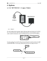
Page 67: ...mpensation procedure An indication that the compass module is connected is the appearance of magnetic HDG reading on navigation page 3 of the LX 7007 PRO IGC The compass module not only permits the display of magnetic heading but also permits the calculation of the wind vector in straight flight The wind vector is calculated using the triangle of velocities method where the vectors of ground speed...

Page 68: ...mentioned above the arrows should be aligned accurately in the flight direction and parallel to the fore and aft axis of the glider For a proper installation a plane area parallel to the horizontal plane is needed 6 1 2 2 First test after installation An external reference compass is required which can either be a prismatic landing compass or a calibrated compass base on the airfield surface Using...

Page 69: ...t in one of the three Nav Pages the wind menu just press ENTER when you are on one of the Nav Pages move the cursor onto WIND and press ENTER again Then choose the item COMPASS Please Note The wind calculation with the compass works exclusively in straight flight The calculation is started when the following conditions are fulfilled for at least 5 sec Speed should be constant It should vary not mo...

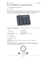
Page 70: ...e function there are no combinations or double functions All keys correspond 100 to the LX 7007 PRO IGC usage philosophy Remote LX 7007 PRO IGC MODE MODE Mode Selector knob Up down selector knob ESC EVENT ENTER MC START ESC EVENT ENTER MC START ON key ZOOM ZOOM ZOOM knob 6 2 1 2 Getting started The following parts are included LX Remote unit Flexible cable with telephone connectors on both ends ca...

Page 71: ...ETUP INPUT 6 2 2 2 LX 7007 PRO IGC Remote K configuration There are two units Leather coated stick with built in electronic Note The stick is delivered in two diameters 20mm and 24 mm LS gliders requests 24mm all other glider types will accept 20mm Interface printed circuit board to connecting wires coming from the stick to the LX 7007 485 system bus 6 2 2 3 Stick handle with keys The original sti...

Page 72: ...LX7007 pro IGC V1 0 Apr 2005 Page 72 7 Revision history Apr 2005 1 0 NEW DONE ...

Reviews: