4
Note:
For systems controlled by a Quantum
®
TZTUFNBMM
programming is done using the Q-Design
TM
software. This
programming section applies only to systems controlled using a
GRAFIK Eye
®
QS control unit.
Assigning a Single DMX Channel to a
GRAFIK Eye
®
QS Zone
Most DMX fixtures use single-channel assignment. If you are
VTJOHTJOHMFDIBOOFM%.9GPMMPXUIFJOTUSVDUJPOTCFMPX*G
ZPVS%.9GJYUVSFIBTDIBOOFMT 3(#PS$.:SFGFSUPUIF
instructions to the right for 3-channel DMX assignment.
1. Enter programming mode on the
GRAFIK Eye
®
QS. Choose “Zone
Setup” then “Load Type” from the Main
Menu. For the zones you wish to assign
UP%.9DIBOOFMTDIBOHFUIFMPBEUZQF
to DMX.
2. Exit programming mode on the
GRAFIK Eye
®
QS.
3. Enter programming mode on the
QSE-CI-DMX: Press and hold the
programming button for 3 seconds.
5IF4UBUVT-&%XJMMCMJOLSBQJEMZ0O
any GRAFIK Eye
®
QS control units on
UIFMJOLUIF[POF-&%TXJMMJOEJDBUF
their status:
-&%TPGBTTJHOFE[POFTXJMMHPUPGVMMPO BMM-&%TMJUUIFOGMBTI
and all LEDs of unassigned zones will go to Off. To assign a DMX
$IBOOFMUPB[POFQSFTT;POF3BJTFUPVOBTTJHOQSFTT;POF
-PXFS
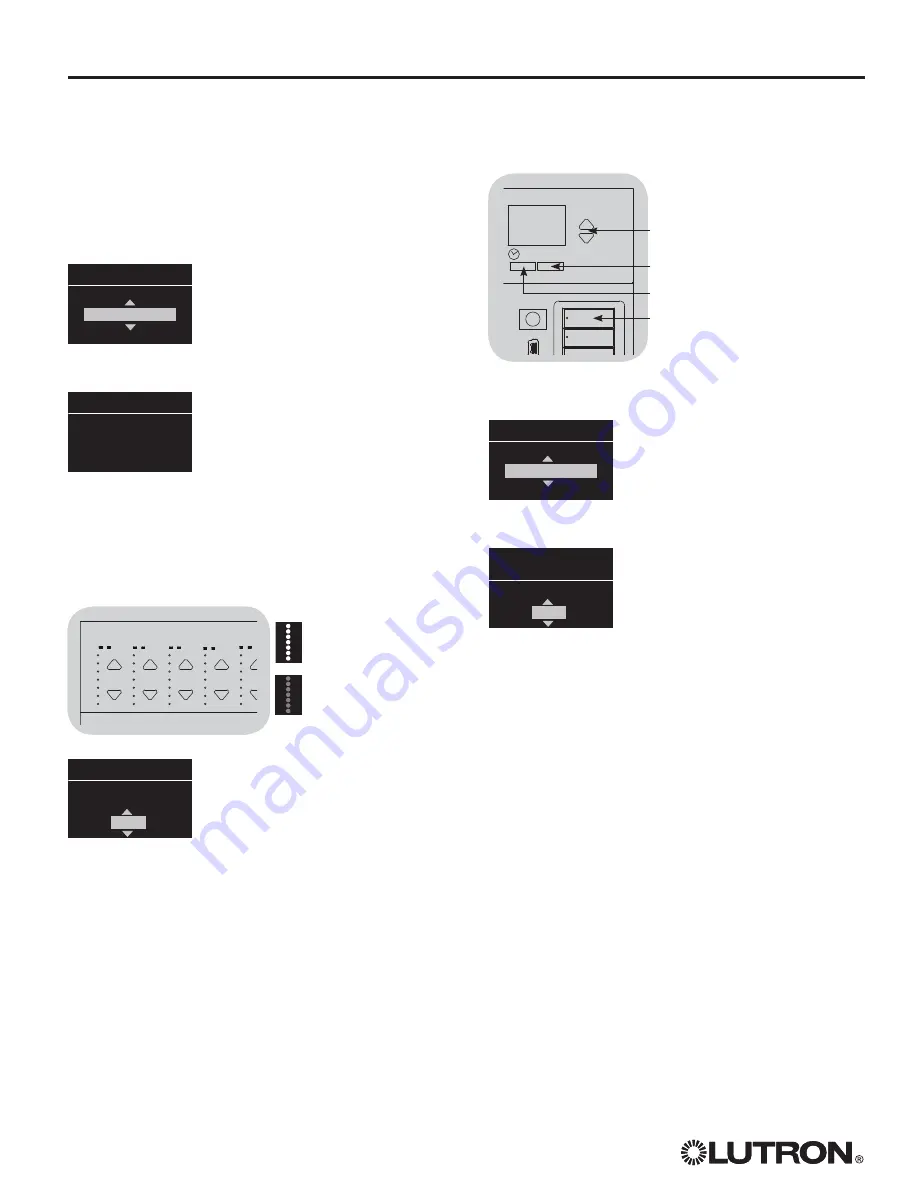
4. The GRAFIK Eye
®
QS will display the
selected zone and an unassigned
%.9DIBOOFM6TFUIFNBTUFSCVUUPOT
on the GRAFIK Eye
®
QS to choose a
DMX channel (from 1 to 512) for this
zone. Press the Scene 1 button on the
GRAFIK Eye
®
QS to cause the currently
selected DMX channel to flash. Press
OK to assign the selected DMX channel
to the selected zone.
Note:
Do not use the Flash feature with DMX devices containing
NPWJOHQBSUT TIBEFNPUPSTNPUPSJ[FEMJHIUGJYUVSFTTNPLF
QSPEVDJOHNBDIJOFTFUDUPBWPJEEBNBHJOHUIPTFEFWJDFTPS
causing unexpected motion. If the selected channel is already
BTTJHOFEUPB[POFUIF(3"'*,&ZF
®
QS will prompt you to
confirm replacing the channel with the new selection. Press OK
to confirm the replacement.
Zone 4
Choose Channel on
DMX AABB-CCEE
14
DMX Prog
Push
Zone R to Assign
Zone L to Unassign
Zone 4
DMX
GRAFIK Eye
®
QS control unit
Zone Buttons
1
2
3
4
5
9
10
11
12
13
Zone LEDs full on and
flash (zone
assigned
to
QSE-CI-DMX)
Zone LEDs Off
(zone
unassigned
to QSE-CI-DMX)
5. Repeat step 4 for each DMX zone.
6. Exit programming mode: Press and hold the programming
CVUUPOPOUIF24&$*%.9GPSTFDPOET5IF4UBUVT-&%XJMM
SFTVNFTMPXCMJOLJOH PODFQFSTFDPOE
Assigning RGB/CMY DMX Channels
(3-Channel DMX) to GRAFIK Eye
®
QS Zones
1. Enter programming mode on the
GRAFIK Eye
®
QS. Choose “Zone
Setup” then “Load Type” from the
Main Menu. For the zones you wish to
BTTJHOUP3(#$.:DIBOOFMTDIBOHF
the load type to RGB/CMY DMX.
2. Exit programming mode on the
GRAFIK Eye
®
QS.
3. Enter programming mode on the
QSE-CI-DMX: Press and hold the
programming button for 3 seconds.
5IF4UBUVT-&%XJMMCMJOLSBQJEMZ
On any GRAFIK Eye
®
control units on
UIFMJOLUIF[POF-&%TXJMMJOEJDBUF
their status: LEDs of assigned zones
XJMMHPUPGVMMPO BMM-&%TMJUBOE-&%T
of unassigned zones will go to full off
(all LEDs off). To assign a DMX Channel
UPB[POFQSFTT;POF3BJTFUP
VOBTTJHOQSFTT;POF-PXFS
4. The GRAFIK Eye
®
QS will display the selected zone and an
VOBTTJHOFE%.9DIBOOFM6TFUIFNBTUFSCVUUPOTPOUIF
GRAFIK Eye
®
QS to choose a DMX component channel (from 1
to 512) for this zone. Press the Scene 1 button on the GRAFIK
Eye
®
QS to cause the currently selected DMX channel to flash.
Press OK to assign the selected DMX channel to the selected
zone and proceed. Repeat for all 3 channels.
*GUIFTFMFDUFEDIBOOFMJTBMSFBEZBTTJHOFEUPB[POFUIF(3"'*,
Eye
®
QS will prompt you to confirm replacing the channel with
the new selection. Press OK to confirm the replacement.
5. Repeat step 4 for all the RGB/CMY DMX zones.
6. Exit programming mode: Press and hold the programming
CVUUPOPOUIF24&$*%.9GPSTFDPOET5IF4UBUVT-&%XJMM
SFTVNFTMPXCMJOLJOH PODFQFSTFDPOE
Note:
The RGB/CMY table can be edited to map a zone
intensity to a specific RGB/CMY color using the color
configuration tool for the QSE-CI-DMX (available at
www.lutron.com/qs).
Zone 4- RGB/CMY
Component 1 channel
14
Zone 4
RGB/CMY DMX
OK
Master buttons
Scene 1 button
OK button
5JNFDMPDL CBDLCVUUPO
Programming


