background image


DP16-910B-VS                              09


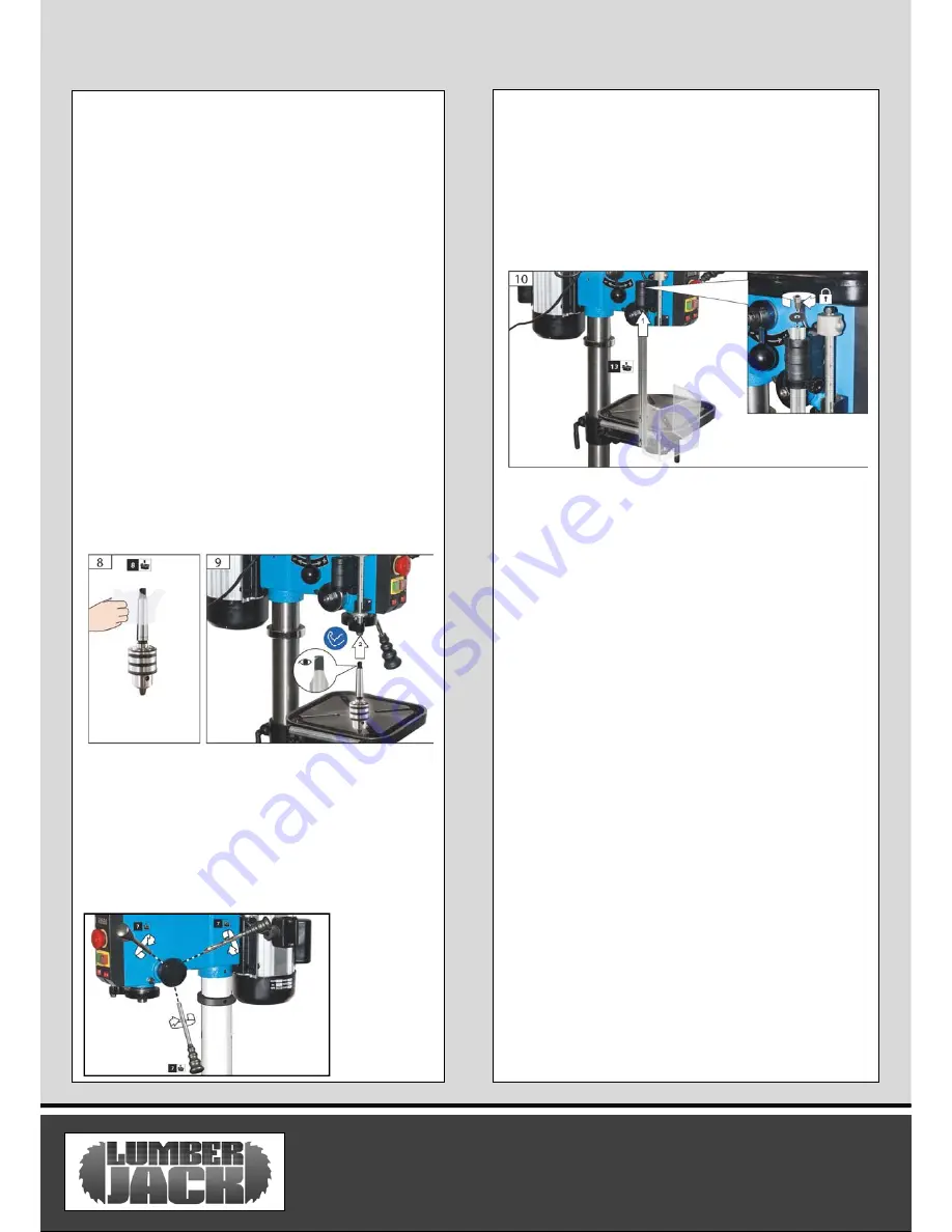
Installation the chuck 

1.Locate the chuck in the box of parts. 
2.Clean out the tapered hole in the chuck, also 
clean the spindle nose with a clean cloth. Make 
sure there are no foreign particles sticking to the 
surfaces. The slightest piece of dirt on the 
spindle nose or the chuck will prevent the chuck 
from seating properly. This will cause the drill to 
“wobble .  

NOTE: 

If the tapered hole in the chuck is 

extremely dirty, use a cleaning solvent on a clean 
cloth.  
3.Push the chuck up on the spindle nose as far as 
it will go.  
4. Turn the chuck sleeve clockwise and open the 
chuck jaws completely.  
5. Lightly tap the nose of the chuck with a piece 
of wood to insure the proper seating of the 
chuck on the spindle.  
 

Installation the feed handles 

1. Locate the three feed handles among the 
loose parts..  
2. Screw the feed handle tightly into the 
threaded holes in the hub. 

Installing the chuck guard 

1.The chuck guard insert the micro switch seat set 
and then by tightening the screw by tool. 

WARNING!: 

To


avoid possible injury, keep the 

guard in place and in proper working order while 
operating. 


ASSEMBLY INSTRUCTIONS 

Summary of Contents for DP16-910B-VS

Page 1: ...DP16 910B VS SAFETY AND OPERATING MANUAL 16mm Bench Top Drill Press DP16 910B VS ORIGINAL INSTRUCTIONS...

Page 2: ...ith all information necessary for using the product safely and to ensure its long service life Closely observe all safety information in these instructions General Power Tool Safety Warnings Symbols C...

Page 3: ...s that have the switch on invites accidents d Remove any adjusting key or wrench before turning the power tool on A wrench or a key left attached to a rotating part of the power tool may result in per...

Page 4: ...h the power tool or these instructions to operate the power tool Power tools are dangerous in the hands of untrained users e Maintain power tools Check for misalignment or binding of moving parts brea...

Page 5: ...while drilling make sure the piece is secured with a vice never hold the workpiece by hand Never keep your fingers near where they could touch the drill in case the piece moves suddenly 8 4Do not use...

Page 6: ...d off of a mirror or any other reflective surfaces can also be dangerous h Always wear laser protective eyewear when working on or near reflective surfaces i Do not attempt to activate the laser when...

Page 7: ...mpact of noise can cause damage to hearing Amperes 7 5M 15M 25M 30M 45M 60M 0 2 0 6 6 6 6 6 6 2 1 3 4 6 6 6 6 6 6 3 5 5 0 6 6 6 6 10 15 5 1 7 1 10 10 10 10 15 15 7 1 12 0 15 15 15 15 20 20 12 1 20 0 2...

Page 8: ...Max Spindle Travel 90mm Drill Capacity 16mm Chuck Capacity 16mm Max Distance From Chuck to the table 275mm Max Distance From Chuck to the base 445mm Table Size 243X243mm Base Size 450X270mm Over all...

Page 9: ...le 12 Support lock 13 Table Bevel Lock 14 Table rotation lock 15 Speed variator Unpacking Instructions 1 Separate all parts from packaging materials and check all items are accounted for 2 Remove the...

Page 10: ...ssembly 1 Position the base on the floor Remove the protective covering and discard 2 Remove protective sleeve from the column and discard Place the column assembly on the base align the holes in the...

Page 11: ...on a clean cloth 3 Push the chuck up on the spindle nose as far as it will go 4 Turn the chuck sleeve clockwise and open the chuck jaws completely 5 Lightly tap the nose of the chuck with a piece of...

Page 12: ...se to loosen Drilling to a specific depth To drill a blind hole not all the way through to a given depth proceed as follows 1 Mark the depth of the hole on the workpiece 2 Loosen the depth scale lock...

Page 13: ...e notch loosen inner nut approx 1 8 until the notch disengages from the boss on the head Do not remove this nut 6 Carefully turn screwdriver counterclockwise and engage the next notch in the boss Do n...

Page 14: ...Do not look directly at the laser beams Do not aim the laser beams at any person or any object other than your workpiece If you desire using the dual laser guides use the laser switch to turn them On...

Page 15: ...ece as the drill breaks through To keep the back up material from spinning out of control it must come in contact with the left side of the column as illustrated in WARNING To prevent the workpiece or...

Page 16: ...odpiece torn loose from hand 1 Not supported or clamped properly 1 Support workpiece or clamp it Drill bit binds in workpiece Excessive drill bit run out or wobble 1 Workpiece pinching drill bit or ex...

Page 17: ...pected to wear at different rates depending on usage 1 2 7 The product has not been used for hire purposes 1 2 8 The product has been purchased by you as the guarantee is not transferable from a priva...

Page 18: ...product for any commercial business or resale purposes and we have no liability to you for any loss of profit loss of business business interruption or loss of business opportunity 3 2 This Guarantee...

Page 19: ...nch Top Drill Press DP16 910B VS Is in compliance with the regulations included in the Directives 2006 95 EC EC DECLARATION OF CONFORMITY Certificate for EC type examination delivered by T V S D Produ...

Page 20: ...pan head screws 12 Support 39 Light switch 13 Collar rack 40 Magntic switch 14 Hexbolt M12x25 41 Emergency stop switch 15 Arm table with scale 42 Plate display 16 Table 43 Box switch 17 Extension rod...

Page 21: ...ring 66 LED worklight 95 Spline housing 67 Laser 96 Flat 68 Soket head cap screw 97 Circlip ring 69 Gear shaft 98 Guard 70 Handle seat 99 Fixed spindle pulley 71 Handle lever 100 Activity spindle pull...

Page 22: ...R6V 01 AIR6V 01 AIR6V 01 DP16 910B VS 20 No Description No Description 113 Chuck guard 117 Micro switch 114 Washer 118 Cover Micro switch 115 Nut 119 Self tapping screw 116 Plate Micro switch Parts Li...

Page 23: ...DP16 910B VS 21 Parts Diagram...

Reviews: