


363-205-401
Power Up: DLP-535
Issue 7, March 1997
Page 7 of 8
25.
!
DANGER:
After connectors are mated, power bus will be "live" (i.e., have voltage on
it).
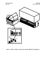
Connect together gray connectors on STR( ) (1, 2, or 3) battery string cable
and STR( ) (1, 2, or 3) cable from control & distribution panel.
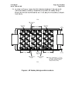
26. Dress and secure cables to the top of the battery compartment as necessary
to keep them above batteries (in case of flood).
27.
NOTE:
To measure battery string voltage accurately, disconnect any battery
strings other than battery string being measured. [To disconnect other
battery strings, unplug STR( ) battery string cable connector (gray) from
STR( ) battery cable connector (gray) from control & distribution panel.]
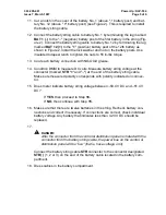
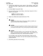
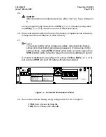
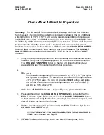
On control & distribution panel [Figure 3], connect DMM to BAT( ) (1, 2, or 3)
test point and PVR test point for battery string being installed.
Figure 3 – Control & Distribution Panel
28. Does meter indicate battery string voltage of 49.5 V DC or higher?
If YES, then proceed to Step 30.
If NO, then continue with Step 29.
ed-83114-30
CB6
CB5
CB4
CB3
CB2
CB1
normal
disconnect
low volt
discharge
bat on
TEST
OPEN BAT
BAT2
BAT1
BAT3
BATC
BAT4
BATTERY CURRENT:
OPEN BATTERY TEST
Control & distribution
rectifier 3 * rc3 - RR
battery 4 * bat4 - batc
battery 3 * bat3 - batc
battery 2 * bat2 - batc
Battery 1 * bat1 - batc
TO MEASURE * USE TEST POINTS
rectifier 2 * rc2 - rr
rectifier 1 * rc1 - rr
rectifier current:
plant current * pc - pcr
plant voltage * pv - pvr
To measure * use test points
POWER PLANT TEST POINTS
RC1
RC2
PVR
RR
PV
RC3
PC
PCR