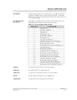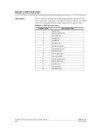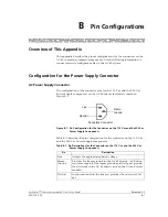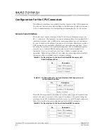
255-700-025
B-1
PacketStar
™
Access Concentrator 60 User Guide
, Issue 1
Release 6.3.0
B
Pin Configurations
Overview of This Appendix
This appendix describes the pinout configurations for the connectors on the
AC 60 common equipment components. Use the following information to
connect correctly configured cables to the AC 60 system.
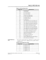
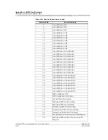
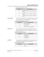
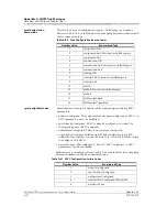
Configuration for the Power Supply Connector
AC Power Supply Connector
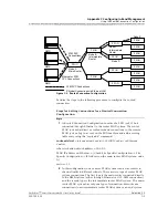
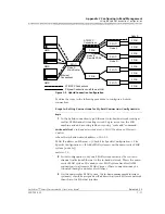
The configuration of the connector pins for the 110 V ac and the 220 V ac
Power Supply components on the AC 60 chassis faceplate is shown in
Figure B-1.
Table B-1 describes the pin configuration for the connector on the 110 V ac
and the 220 V ac Power Supply components.
Figure B-1. Pin Configuration for the Connector on the 110 V ac and the 220 V ac
Power Supply Components
Table B-1. Pin Descriptions for the Connector on the 110 V ac and the 220 V ac
Power Supply Components
Pin
Description
Line
Accepts the appropriate phased voltage.
Frame-
Ground
Provides the frame ground for the AC 60 chassis. A 2 K ohm
resistance separates the frame ground and the logical ground
for all circuits in the AC 60 chassis, and on the I/O and server
modules.
Neutral
In conjunction with the line pin, provides the reference volt-
age.
Line
Neutral
Frame
Ground
Faceplate Connector

