background image

Installation Manual of HD-TVI Speed Dome 

16 


faraway. At this time, the dome will be uncontrollable, or self-running, etc. 
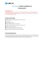
1#

6#

15#

32#

Controller


Figure A-4 Star Shape Connection


For  such  case,  the best way  is  adding  a  RS485  distributor.  This  product  can  effectively  change  the 
star-shape  connection  to  which  satisfies  the  requirement  of  RS485  industry  standard,  in  order  to 
avoid those problems and improve the communication reliability. Show as figure 5.   

A+

B-

485 Distributor

120

Ω

1#

2#

16#

120

Ω

120

Ω


Figure A-5


RS485 Distributor


Troubleshooting of RS485 communication 

Problem


Possible Reasons 

To Solve the Problem


The speed 
dome does 
the 
self-test 
action but 
cannot be 
controlled 
remotely.


1. The address or baudrate of the 
speed dome does not match with 
those of remote control device. 

1. Adjust the address and 
baudrate of the remote control 
device to match with those of the 
speed dome. 

2. The wire RS485+ connects to 
the interface RS485- and wire 
RS485- connects to the interface 
RS485+. 

2. Connect the wire RS485+ to the 
interface RS485+ and wire RS485- 
to the interface RS485-. 

3. The RS485 wire is 
disconnected. 

3. Reconnect the RS485 wire 
tightly. 

4. RS485 wire is broken. 

4. Change a RS485 wire. 

The speed 

1. The connection is loose. 

1. Reconnect the RS485 wire 

Summary of Contents for PTZH213X23

Page 1: ...HD TVI Speed Dome Installation Manual...

Page 2: ...ntact the dealer This manual is applicable to HD TVI Speed Domes This manual may contain several technically inaccurate points or printing errors and the content is subject to change without notice Th...

Page 3: ...erence received including interference that may cause undesired operation EU Conformity Statement This product and if applicable the supplied accessories too are marked with CE and comply therefore wi...

Page 4: ...cted on the power socket When the product is installed on wall or ceiling the device shall be firmly fixed If smoke odors or noise rise from the device turn off the power at once and unplug the power...

Page 5: ...at the same time Please use the provided glove when open up the dome cover avoid direct contact with the dome cover because the acidic sweat of the fingers may erode the surface coating of the dome c...

Page 6: ...DIP Switch Settings 8 2 3 Wiring and Installation 10 2 3 1 Wiring 10 2 3 2 Installing the Bracket 10 2 3 3 Set the DIP Switch 12 2 3 4 Installing the Speed Dome 12 Appendix 14 Appendix 1 Lightning Sur...

Page 7: ...the dome and the mount Preparing Cables Choose the video cable according to the transmission distance the minimum requirement for the coaxial video cable are shown as follows 75 impedance 100 copper c...

Page 8: ...eparation Wiring Installing Bracket Setting DIP Switch Installing Speed Dome Connecting Cables Power on Self test End Succeeded Failed No Yes Figure 2 1 Installation Flow Diagram 2 1 Cable Description...

Page 9: ...RS485 485 control VIDEO Coaxial and analog video output 2 2 DIP Switch Settings Two DIP switches SW1 and SW2 are for setting the speed dome address baudrate protocol etc with value ON 1 and OFF 0 The...

Page 10: ...F ON OFF OFF OFF OFF OFF OFF 3 ON ON OFF OFF OFF OFF OFF OFF 255 ON ON ON ON ON ON ON ON Baudrate Settings The No 1 2 and 3 of SW2 switch are for setting the baudrate of the speed dome standing for 24...

Page 11: ...n environment and planning the wiring is highly recommended before the accurate deployment of the wire is implemented in order to provide a safe and steady power supply and a reasonable wiring route G...

Page 12: ...own in the figure below Figure 2 5 Wall Mount Bracket Nuts and Flat Washers 2 Drill 4 screw holes in the wall according to the holes of the mount and then insert M8 expansion screws not supplied into...

Page 13: ...refer to the Section 2 2 DIP Switch Settings for DIP switch settings 2 3 4 Installing the Speed Dome The sketched of installing the speed dome are for reference only Steps 1 Hang the safety rope to t...

Page 14: ...Installation Manual of HD TVI Speed Dome 13 Figure 2 9 Tighten the Lock Screws...

Page 15: ...g protection apparatus and lightning conductor are necessary to be added The design of lightning protection and grounding of the outdoor devices and cables should be considered together with the light...

Page 16: ...ference situation or there are lots of devices are added to the bus on the contrary the transmission distance will be increased Connection Methods RS485 industry bus standard require daisy chain conne...

Page 17: ...roubleshooting of RS485 communication Problem Possible Reasons To Solve the Problem The speed dome does the self test action but cannot be controlled remotely 1 The address or baudrate of the speed do...

Page 18: ...Solve the Problem dome can be controlled but not smoothly tightly 2 RS485 or RS485 wire is broken 2 Change a RS485 wire 3 The speed dome is too far away from the remote control device 3 Add a terminal...

Page 19: ...ed as the minimum wire gauge 0 8000 1 000 1 250 2 000 10 283 86 451 137 716 218 1811 551 20 141 42 225 68 358 109 905 275 30 94 28 150 45 238 72 603 183 40 70 21 112 34 179 54 452 137 50 56 17 90 27 1...

Page 20: ...e mm American Wire Gauge AWG British Wire Gauge SWG Cross sectional Area of Bare Wire mm2 0 750 21 0 4417 0 800 20 21 0 5027 0 900 19 20 0 6362 1 000 18 19 0 7854 1 250 16 18 1 2266 1 500 15 17 1 7663...

Reviews: