Installation Manual of HD-TVI Speed Dome
8
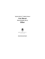
RED AC24V
YELLOW/GREEN GND
BLACK AC24V
①
YELLOW R485-
ORANGE R485+
②
Video Output
Yellow&Green
Yellow
Orange
Black
Red
①
②
Figure 2-2
Cables of Speed Dome
Name
Description
AC24V
Power supply
RS485+/-
485 control
VIDEO
Coaxial and analog video output
2.2
DIP Switch Settings
Two DIP switches
SW1
and
SW2
are for setting the speed dome address, baudrate, protocol, etc.,
with value ON=1 and OFF=0. The switch label is on the back of the SWITCH cover as shown in Figure
2-3.
Each number of the switch represents a DIP value, ranging from 1 to 8 for the lowest to highest.
SW1
SW2
Figure 2-3
Label of DIP Switch for IR Speed Dome