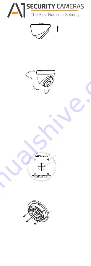
Tilt Position
[0°to 75°]
Pan Position
[0° to 360°]
Rotation Position
[0°to 360°]
Figure 2-4 Secure the Camera with Mounting Base
8.
Connect the corresponding cables, such as power
cord, and video cable.
9.
Power on the camera to check whether the image
on the monitor is gotten from the optimum angle. If
not, adjust the camera according to the figure below
to get an optimum angle.
Figure 2-5 3-axis Adjustment
1). Hold the camera body and rotate the enclosure
to adjust the pan position [0°to 360°].
2). Move the camera body up and down to adjust
the tilt position [0°to 75°].
3). Rotate the camera body to adjust the rotation
position [0°to 360°].
2.1.2 Mounting with Inclined Base
Steps:
1. Paste the drill template (supplied) to the place
where you want to install the camera.
2. Drill screw holes, and the cable hole on the
ceiling/wall according to the supplied drill template.
Screw Hole
Cable
Hole
Figure 2-6 The Drill Template
Inclined
Base Cover
3. Disassemble the inclined base by the screw driver.
4. Install the turret camera’s mounting base on the
inclined base cover with three PM4 screws.
Figure 2-7 Install Turret Camera’s Mounting Base
5.
Install the inclined base’s body on the ceiling/wall
with four PA4
×
25 screws, as shown in Figure 2-8.
Available from A1 Security Cameras
www.a1securitycameras.com email: [email protected]


