


LSI LASTEM M-Log – User’s manual
11
3
8
9
10
11
23
2
21
22
4
24
25
26
27
Digital
input
Signal
GND
E
F
G
5
12
13
14
15 or 16
Actuator/Alarm output on the serial connector
+V
0V
Pin 9
Pin 5
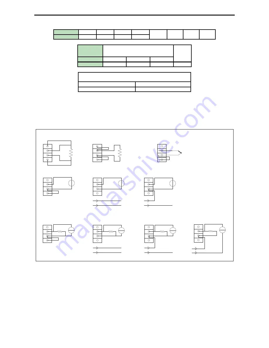
The following pictures explain in detail the connections of all types of sensors, both analogue and
digital.
Sensors with analogue signal (in differential mode):
A
B
C
D
A
B
C
D
A
B
C
D
A
B
C
D
A
B
C
D
4 wires resistance
2 wires resistance
Thermocouple
Voltage signal from externally
powered sensor
Voltage signal from 4 wires
sensor powered (fixed or
switched) from E-Log
0 V
+12V (fixed or switched)
Probe power supply
-
+
A
B
C
D
Current signal from externally
powered probe
Rx
A
B
C
D
Current signal from 4 wires sensor
powered (fixed or switched) from
E-Log
0 V
+12V (fixed or switched)
Probe power supply
-
+
Rx
A
B
C
D
Rx
Current signal from 2 wires probe
(powered from signal wires)
+12V (fixed or switched)
0 V
+
+
+
+
+
+
A
B
C
D
Voltage signal from 3 wires
sensor powered (fixed or
switched) from E-Log
+12V (fixed or switched)
Probe power supply with 0V
as signal common
+
+
0 V
A
B
C
D
Current signal from 3 wires
sensor powered (fixed or
switched) from E-Log
0 V
+12V (fixed or switched)
+
Rx
+
Alimentazione sensore con 0V
comune a segnale
The drop resistance, indicated by Rx, is used to return a voltage signal from the current generated
by the sensor. Program
3DOM
supplies a library for the setting of the LSI LASTEM sensors,
including some powered outputs; for such models the settings have been arranged to use the
energized scale -300÷1200 mV, thus being able to use 50
Ω
drop resistances
.
Sensors with digital signal:


