background image


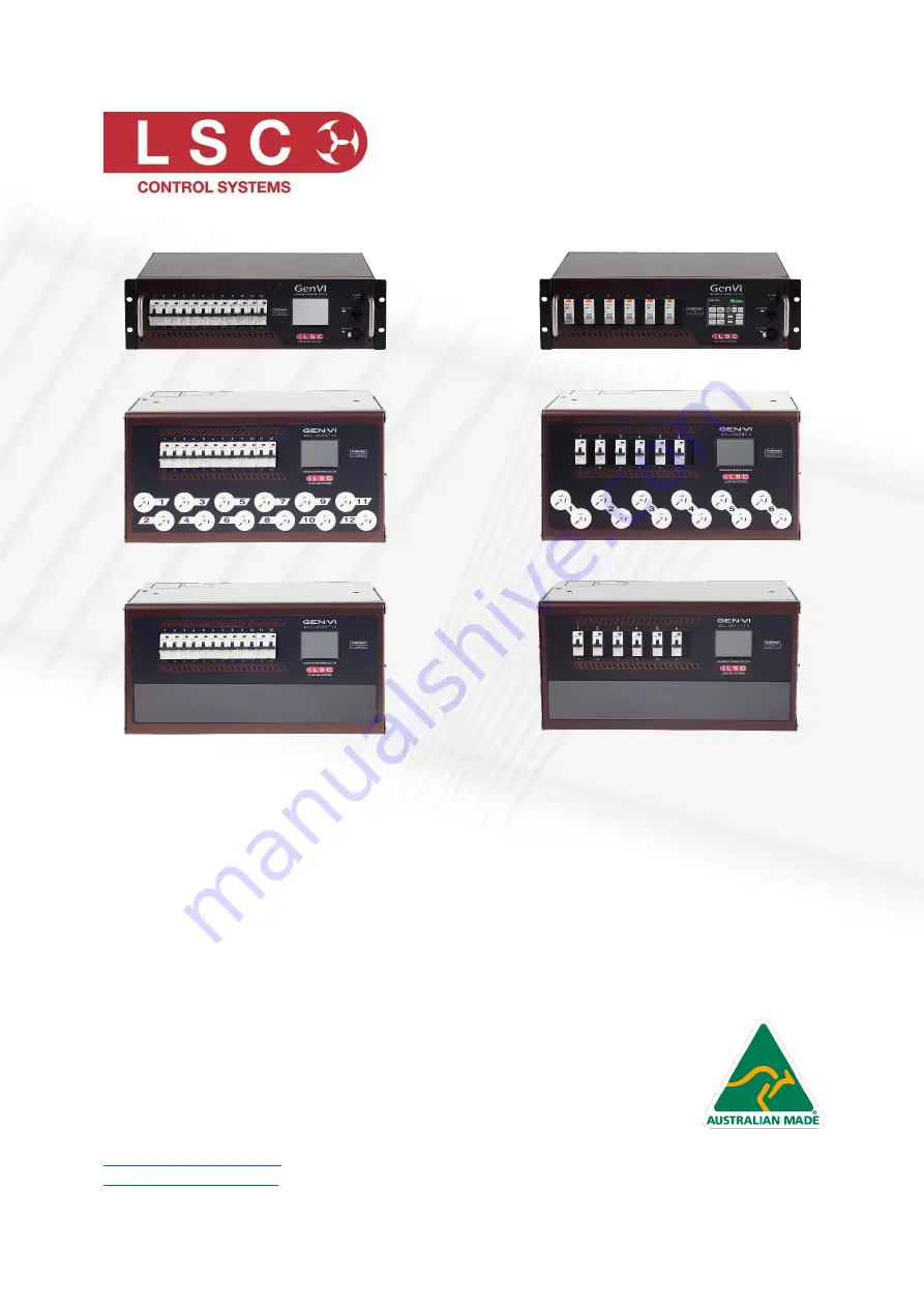
12 Channel Rack Mount 


6 Channel Rack Mount


12 Channel Wall Mount


6 Channel Wall Mount


12 Channel Wall Mount 

Hardwired


6 Channel Wall Mount 

Hardwired


GenVI  
Advanced Dimming and Power 
Switching System 

User Manual 


LSC Control Systems © 
+61 3 9702 8000 

[email protected].au


www.lsccontrol.com.au


V4.02 

August 2022 

Summary of Contents for GEN12/10A

Page 1: ...Wall Mount 6 Channel Wall Mount 12 Channel Wall Mount Hardwired 6 Channel Wall Mount Hardwired GenVI Advanced Dimming and Power Switching System User Manual LSC Control Systems 61 3 9702 8000 info lsc...

Page 2: ...out by LSC Control Systems Pty Ltd or its authorised service agents No liability will be accepted whatsoever for any loss or damage caused by service maintenance or repair by unauthorised personnel I...

Page 3: ...I 10 3 1 2 Wallmount GEN VI 10 3 2 100 120VAC Input Power 11 3 3 Output Connectors 11 4 Installation 12 4 1 Safety 12 4 2 Unpacking 12 4 3 Installation 12 4 3 1 Rackmount GEN VI 12 4 3 2 Wall mount GE...

Page 4: ...nnels Menu 29 5 10 1 Min Level 31 5 10 2 Max Level 31 5 10 3 Curve 31 5 10 4 Source DMX or Auto Power 33 5 11 Colour Theme Menu 33 5 12 System Menu 33 5 12 1 Code Software Upgrade 34 5 12 2 Reset 34 5...

Page 5: ...42 10 3 Opto isolated Problems 42 10 4 Hard Firing 42 10 5 The Proof 43 11 Specifications and Output Options 44 11 1 Rackmount GEN VI 44 11 2 Wallmount Gen VI 45 11 3 Socapex Pinouts 46 11 4 Harting W...

Page 6: ...1 11 and RDM E1 20 compliant control If DMX is lost the GEN VI can either hold the last values or fade to a DMX Loss memory after a programmable delay RCBO Residual Current Breaker with Overcurrent pe...

Page 7: ...X signal exceeds 60 The channel will switch OFF when the DMX signal drops below 40 Auto Power Channels configured for Auto Power are switched on when the lighting console is turned on and a valid DMX...

Page 8: ...VI channel can be configured to be either A DMX controlled dimmer A DMX controlled switch TruPower An Auto Power switch turns on when a DMX signal is present 2 2 1 Dimmer or TruPower Switch Channels...

Page 9: ...on the input to the GEN VI regardless of actual DMX levels When the DMX signal ceases the channels will switch off after a user programmed time Auto Power can only be selected if the channel is set to...

Page 10: ...through connectors load RCBO s Residual Current Breaker RCD GFI with Overcurrent and Neutral disconnect SD card slot used for software upgrades and LCD touch screen Do not use sharp objects to operat...

Page 11: ...al output terminals 3 2 100 120VAC Input Power GEN VI can be supplied from the factory for 100 120VAC input power operation 3 3 Output Connectors Various output connector options are available See sec...

Page 12: ...el The ventilation holes on the sides of the unit must be kept clear 4 3 2 Wall mount GEN VI The wall mount version is comprised of two sections The front section containing all of the electronics is...

Page 13: ...versions only 10 Amp output versions Un plug the load connector plugs from the load terminal blocks on the rear section These connections are tight and will need to be prised out 25 Amp output version...

Page 14: ...h the Redback patch system up to 4 x Gen VI wallmount dimmers can be installed each side of the patch bay allowing for 96 channels of dimming power distro and patch bay to be located in an area of onl...

Page 15: ...ints to connect the incoming three phase supply For hard wired installations there are two large knock out panels located on the upper left hand region These knock out panels allow wiring to enter and...

Page 16: ...age The DMX Address home page has two formats If a 1 to 1 patch is implemented via the DMX Address button it shows the DMX addresses of the first and last channels of the dimmer in a large and small f...

Page 17: ...ontrol Red Rigger control via the touch screen Blue Auto power or DMX Backup DMX loss memory Channels are controlled on a HTP highest Takes Precedence basis If multiple sources are controlling a chann...

Page 18: ...s been pressed the name and logo cannot be changed without contacting the factory This acts as a deterrent against theft of your APS Pressing Owner allows you to enter a permanent name for the dimmer...

Page 19: ...ling fan The animated fan symbol is displayed when the fan is running The fan speed can be controlled See section 5 12 3 The letter C is displayed beside the fan symbol if the speed has been set to Co...

Page 20: ...tual faders or touch a fader then use the or buttons TruPower channels have an On Off push button switch instead of a fader The button turns green when it is on Press or to select more channels When f...

Page 21: ...Dim TruPower DMX Set DMX Term Fast Configuration of either Dimming or TruPower switched for each channel Patch View DMX Input levels Edit DMX Loss Memory Delay Time Fade In Out DMX Loss memory Enable...

Page 22: ...mode Configure your channels then press Save Note Changing a channel from TruPower to Dimming mode can potentially damage connected equipment that should not be connected to a dimmed output If you ch...

Page 23: ...dually patch dimmers channels to DMX slots Individual patches are required when A particular DMX slot number from the lighting controller is to control a particular GEN VI dimmer channel number A sing...

Page 24: ...nd full on If you require smoother fades the GEN VI dimmer can be set to 16bit mode where each dimmer channel uses 2 DMX slots to control its level This gives 65536 discrete levels when fading from of...

Page 25: ...shows a bargarph display of the current DMX Loss memory if any and also its fade time in seconds For example When you press the DMX Loss Memory menu allows you to create or edit the DMX Loss Memory by...

Page 26: ...the keypad to set the level then press Apply 5 8 3 2 Taking a Snapshot To create a memory by taking a snapshot press Snap from the DMX Loss Memory menu above Pressing DMX will take a snapshot of the c...

Page 27: ...t to the GEN VI and switches them OFF when the lighting controller is turned off and the DMX signal is not present A Hold Time can be set to prevent fixtures being turned off if there is a short inter...

Page 28: ...5 Auto Power Mode To set a channel to operate in Auto Power mode you must first set the channel to TruPower mode and then set its Control Source to Auto Power To set a channel to TruPower mode from e...

Page 29: ...Selecting Config Channels provides menus for configuring the following parameters for each channel Min Minimum Level Max Maximum Level Curve The choices are S curve diming L Linear dimming TruPower or...

Page 30: ...r last channel Use the or buttons to see the other groups of 6 channels Use All to select all channels Press None to de select all channels The selected channels are highlighted in the navigator In th...

Page 31: ...seful to Pre Heat lamp filaments Min level is disabled in Tru Power mode 5 10 2 Max Level Select Config Channels select the channel number s then Edit and select the Max Level parameter Max sets the l...

Page 32: ...om the SD card to a computer The file is a text file that you can open in any text editor or spreadsheet program It has one entry per line indicating output level 0 65535 for each of 256 DMX input val...

Page 33: ...etected these channels will remain on for a programmable hold time See section 5 8 4 to set the hold time Channels configured for Auto Power are used to provide switched power whenever the lighting co...

Page 34: ...D card The controller module in the GEN VI knows which filename to look for so only the correct code will be loaded and upgraded Insert the SD card containing both files into the SD card socket on the...

Page 35: ...ts or for archiving The SD card slot is located on the front panel The configuration file name is fixed as GNW_CFG XML If you need to use multiple configurations than you should either use a separate...

Page 36: ...n reveals a Lock keypad Enter a four digit code and the Lock button appears Press Lock to lock the selected level If User or Config are locked the Config button is replaced by a Padlock symbol To unlo...

Page 37: ...show the presence of the input power phases Green indicates power is present Flashing red is not present DMX shows the presence of a DMX control signal Green is DMX present Flashing Red is not present...

Page 38: ...roblem replace the lamp or reduce the load then restore the Circuit Breaker If the Circuit Breaker continues to trip refer the problem to a suitably qualified person If a channel will not turn on chec...

Page 39: ...te monitor and instantly change parameters of connected products Using HOUSTON X you can quickly locate and isolate faults monitor temperatures phase loadings change a channel from dimmer to power swi...

Page 40: ...es in length When several DMX feeds are required to feed different locations DMX512 splitters must be used These provides multiple isolated DMX512 feeds The GEN VI uses a high impedance DMX input circ...

Page 41: ...you have needs to be changed for new RDM hardware This will most commonly mean that DMX splitters and buffers will need to be upgraded to RDM capable devices To utilise RDM you will also need an RDM...

Page 42: ...he dimmer circuitry relies on the connected load to power the triac Therefore the opto isolated dimmer s performance is dependent on the load connected to it In the case of a simple high power load su...

Page 43: ...demonstrations The LSC PTFD dimmers can control all of these devices without any problem Almost all opto isolated dimmers fail this demonstration completely The mirror ball motor does not start or if...

Page 44: ...260V 45 65Hz Hardwired models supplied with L1 L2 L3 N and E terminals for power connection All other models as per below Supplied with 1 2m long H07 rubber 5 core x 6mm cable Export models supplied w...

Page 45: ...oss of signal Protection 12 channel x 10A RCBO breakers with 30mA trip per channel 6 channel x 25A RCBO breakers with 30mA trip per channel Monitoring Phases present DMX RDM temperature and fan monito...

Page 46: ...han 1 Active Pin 1 Chan 7 Active Pin 2 Chan 1 Neutral Pin 2 Chan 7 Neutral Pin 3 Chan 2 Active Pin 3 Chan 8 Active Pin 4 Chan 2 Neutral Pin 4 Chan 8 Neutral Pin 5 Chan 3 Active Pin 5 Chan 9 Active Pin...

Page 47: ...e pin outs are listed in a separate document that is included with your dimmer 12 Feature History The new features added to APS in each software release are listed below Release v4 02 Date 03 Dec 2021...

Page 48: ...Jun 2018 The SD card reader has been revamped so that it can now read exFAT formatted cards The DMX update rate has been increased An upgrade file is now checked for and if present an upgrade button...

Page 49: ...e Gen VI Dimmer from LSC Control Systems Pty Ltd meets all required CE European RCM Australian and UKCA United Kingdom standards European Committee for Electrotechnical Standardization CENELEC Austral...

Reviews: