background image

4 - 13

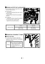
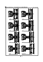
Adjustment range

Lift rod

430~540 mm

(16.9 ~ 21.3in)

Upper link

480~ 700 mm

(18.9 ~ 27.6in)

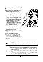
Adjustment of Lift rod and Upper link

z

Do not adjust the lift rod and upper link over the 

described range as below.

z

For lift rod (RH)

- Lift up the lift rod handle and turn left or right to 

adjust the length. 

- Lock the lift rod handle to the lower part after 

adjusting.

z

For upper link

- Lift up the lock spring to release the handle and 

turn the upper link by using the handle.

- Apply the lock spring after adjusting.

Lift rod (LH)

Lift rod (RH)

Upper link

Lift rod handle

Adjustment of stabilizer’s length

Check chain type

z

Turn the knob(2) to adjust the length of the 

stabilizer(1). After the adjustment , let it tightened 

firmly by fixing nut(1).

When adjusting the stabilizer’s 

length, adjust the implement’s 

swinging clearance to be 

20~40mm (0.79~1.57 in.) left 

and right.

Notice

Summary of Contents for XR4040

Page 1: ...lating to Toxic substances 1 14 1 3 Long term storage 1 Preparation for storage 1 15 2 Check Maintenance during storage 1 16 3 Preparation for Reuse 1 16 1 4 Notices for Use Disposal related to the environment 1 17 1 5 Symbols 1 18 1 6 Safety Decals 1 Handling and Maintenance of Safety Decals 1 19 2 Safety Decals and attaching position 1 19 2 Instruction for safe operation 1 The name of each part ...

Page 2: ... and Cabin pillar Cabin type 1 Main gear shift lever Mechanical 3 17 2 Range gear shift lever HST type 3 18 3 Parking brake lever 3 19 4 Differential lock pedal 3 19 5 Work light switch 3 20 6 Window wiper switch Front Rear 3 21 7 Electrical power outlet socket 3 21 8 Indoor light Cabin only 3 22 9 Audio player Cabin only if fitted 3 22 3 3 Left hand controls Cabin type 1 Range gear shift lever Me...

Page 3: ...w to Drive and how to Stop 1 How to drive 4 4 2 Changing speed 4 6 3 Emergency Stop 4 7 4 Stopping tractor 4 8 5 Driving tractor on the road 4 9 6 Parking 4 10 4 3 How to handle new tractor 1 Check points 4 11 2 Notices in handling new Tractor 4 11 4 4 Attaching Implement 1 3 point linkage 4 12 2 Power take off PTO shaft 4 16 3 Hitch and Drawbar optional 4 18 4 7 Pole connector optional 4 19 5 Tec...

Page 4: ...1 Adjustment of brake pedal play 5 14 12 Adjusting HST control linkage HST type 5 15 5 7 Every 50 hour check 1 Lubricating grease nipple 5 16 2 Cleaning of Radiator and Radiator screen 5 16 3 Checking Transmission oil 5 17 4 Checking Front axle oil 5 17 5 Battery check 5 17 6 Air cleaner Dry type 5 17 7 Hydraulic hoses and Leakage 5 17 8 Cleaning Cabin air filters 5 18 5 8 Every 250 hour check 1 R...

Page 5: ... of each part of cooling and heating system 6 1 6 2 How to use air conditioner and heater 1 How to operate air conditioner and heater 6 2 2 Air direction control 6 2 6 3 Every 6 month check 1 Checking refrigerant amount 6 3 2 Cleaning condenser and Radiator screen 6 3 3 Checking leakage 6 3 4 Belt tension adjustment 6 3 6 4 Every year check 1 Compressor check 6 4 2 Control switch check 6 4 6 5 Tro...

Page 6: ... Do not use the tractor without wearing the seat belt and Roll Over Protective Structure ROPS during operations where roll over or tip over hazards exist The ROPS will only be fully effective when the driver remains attached to his seat z Do not use equipment mounted on the tractor which is not correctly matching and firmly fixed Such equipment may increase the risk for roll over and hit the tract...

Page 7: ...o not allow people standing on the access way or step to the cab when the tractor is moving Your view to the left will be obstructed and a rider risks to fall from the tractor during unforeseen or abrupt movements z This tractor has only one operator station and is a one man operated vehicle Other people on or around the tractor during normal operation are not allowed z Always stay clear from impl...

Page 8: ...Identification Your tractor has a exclusive chassis number and engine number marked with product serial number tag to identify the product See Fig 1 1 In case of requesting service or parts from your dealer Dealer will need chassis serial number engine serial number TM number and also running hours displayed on the instrument panel See Fig 1 3 Chassis No Hour meter Engine No Fig 1 4 TM number ...

Page 9: ...afety equipment instead of loose or long clothes Also slippers high heel shoes are not suitable for operation Wear the low shoes or work shoes or boots Warning Do not approach the rotating shaft such as PTO shaft or cooling fan especially with loose clothing and long clothes The entanglement in rotating shaft can cause serious injury or death Stop the engine and be sure PTO shaft is stopped before...

Page 10: ... dealer If not it may cause a reduction of product life failure and serious injury z Restrict Maintenance If you repair or change some components and settings arbitrary the performance of the tractor can NOT be guaranteed and may void the warranty And also maintenance of the heavy weighted parts without special tools can cause serious injury If it is required to check or repair the tractor due to ...

Page 11: ...which can cause death or serious injury in the event of fire tip roll over collision or accident and void the warranty Warning z Level of protection of the FOPS Falling Objects Protective Structure For cabin model it provides protection against falling objects according to OECD code 10 standard The energy level of drop test is 1365 J But it does not mean that the cabin provide full protection agai...

Page 12: ...ened z Place the shuttle lever transmission gear lever in NEUTRAL and especially check if parking brake is applied z Lower the implements on the ground z Ensure that rear view mirrors and the other mirrors if fitted are adjusted correctly and check the operation of the headlights and other lights z Put PTO switch to OFF position If the PTO switch is ON position the engine can NOT be started See Fi...

Page 13: ... 3 Notices while operating using the tractor z Ventilation Warning It is very dangerous to work in a closed area The poisonous exhaust gas may cause serious damage to the human body If you should work in this area make sure to ventilate well and put on the protective mask z When driving the tractor in reverse lower the engine speed Make sure to check if there is any obstacle or person in the rear ...

Page 14: ... additional weights in the rear front of the tractor to keep the balance of the tractor z Obey the traffic rules while driving on public roads Do not exceed the local legal speed limit Use a sing beacon or slow moving vehicle SMV to indicate that the vehicle is slow moving z If you can not drive the tractor due to a failure move the tractor to a safe place and install troubled vehicle safety tripo...

Page 15: ...z Do not attach over weighted implement Before connecting or checking the implement put PTO switch to OFF and place PTO gear lever in NEUTRAL position When attaching or detaching the implement make sure to fix the implement and tighten the three point hitch pins correctly If not the serious troubles and injury can occur during the operation If heavy loaded trailer is connected to 3 point linkage o...

Page 16: ...g wheel If possible run the engine for steering and lubrication z When being towed disengage the 4WD differential lock parking brake and place all gear shift levers in neutral position 6 Notices when transporting the tractor z When transporting the tractor by truck trailer etc use suitable equipment or facilities to load or unload the tractor z Fix the tractor tightly to the vehicle with heavy dut...

Page 17: ... can cause blindness if splashed into eyes Do not touch the battery or liquid by bare hand without gloves or any protection Flush eyes with clean water for about 20 minutes If the electrolyte is splashed into the eyes Get medical attention immediately Do not short circuit the battery posts with metal items Battery post terminals and related accessories contain lead and lead compounds MUST WASH YOU...

Page 18: ...er grade fuels are not held over and used in the winter z Before operating with Bio Diesel contact your authorized dealer for information relating to the use and storage of Bio Diesel z Before servicing the tractor attach a DO NOT OPERATE warning tag to the tractor in an area that will be visible See other side Reason DO NOT OPERATE DO NOT OPERATE Signed by Tel z It is advisable to keep a First ai...

Page 19: ...lope unavoidably while attaching the loaded equipment the tractor may move even if the parking brake is applied Apply the wheel chock and low speed transmission gear as follow Mechanical downhill Reverse 1gear uphill Forward 1gear HST type Lowest gear Caution 9 Notices when leaving the tractor 10 Notices relating to Toxic substances z Exhaust gas and some its constituents of the Diesel engine are ...

Page 20: ...ts concentration z Fill the fuel tank full with fuel z Loosen all drive belts and clean the air cleaner z Loosen the rubber plug if fitted under the clutch chamber to drain water z Remove the battery clean the cover and smear the terminals with grease Place the battery in a ventilated place not less than 10 C 50 F and away from direct sunlight Warning When restarting the engine at the end of long ...

Page 21: ...term storage check each part as below z Check the damaged part or loosen part z Check the leakage of fuel coolant engine oil transmission and front axle oil z Check the level and density of the engine coolant z Check the level of engine transmission rear and front axle oil and fuel For further information refer to the section 5 Lubrication and Maintenance in this manual z Check all the drive belts...

Page 22: ...ission anti freeze solution directly do not throw the exhausted waste oil to any place This may pollute the soil and water seriously and also is prohibited legally If violating you would be responsible for that by civil or criminal case The waste oil must be disposed according to the environment laws 3 Use the product according to the Operator s Manual and if the life of product ended do not throw...

Page 23: ...ward Side lights Headlights upward Work light Light switch Emergency lights Cylinder rod shorten Cylinder rod extend Cylinder rod floating Window wiper Window wiper Washer front Window wiper Washer rear Cruise drive optional Cruise drive release optional Fuel level Refer to operator s Manual Fuel filter Battery charging Caution Transmission oil pressure Engine oil press ure Engine coolant temperat...

Page 24: ...it may cause the death or serious injury If the decals are dirty wash them with soap water and wipe with soft rags Do not use the thinner acetone or other harsh chemicals as it may erase the instructions If the decal is detached or damaged replace it with a new one on original position When cleaning the tractor with pressurized water the decals can be detached If a decal is on a part that is repla...

Page 25: ...1 20 7 8 2 5 4 9 11 12 3 1 Roll Bar 6 10 ...

Page 26: ... hands clothing away from the rotating fan and belts Contact with moving parts may cause loss of fingers or a hand Failure to comply could result in death or serious injury Part No 40239638 5 Location On top of the right hand fender HIGH PRESSURE FLUID HAZARD To prevent serious injury or death Relieve pressure on system before repairing adjusting or disconnecting Wear proper hand and eye protectio...

Page 27: ... Always work with an assistant when lowering or raising the ROPS No roll over protection is provided when ROPS is in lowered position Part No 40008817 7 Location On top of air cleaner support TO PREVENT DEATH OR SERIOUS INJURY High pressure steam and hot water Remove filler cap with extreme care Failure to comply could result in death or serious injury Part No 40239637 8 Location On the right hand...

Page 28: ...e for your protection Pull only from approved drawbar or lower links of 3 point hitch at horizontal position or below Lock tractor brake pedals together for travel on roads or highways Always apply parking brake and shift transmission to neutral before dismounting Always use a seat belt when you operate the tractor Allow no riders on tractor or implements Do not use a seat belt when operating with...

Page 29: ...attach ropes or chains to ROPS for pulling purpose Failure to comply could result in death or serious injury Part No 40234561 11 Location On the right hand pillar for Cabin model On the right hand fender for Roll bar model optional JOYSTICK LEVER USAGE TO AVOID PERSONAL INJURY Wrong operation causes serious injury easily Push the lever 1 in to lock the joystick in neutral Failure to comply could r...

Page 30: ...ruction for safe operation Instrument panel Steering wheel Driver s Seat Sub step Head light Roll bar Safety frame Bonnet Hood Front ballast weight optional Front axle Fender 1 The name of each part Roll Bar type ...

Page 31: ...2 2 Instrument panel Steering wheel Driver s Seat Sub step Head light Cabin Bonnet Hood Front ballast weight optional Front axle Fender Cabin type ...

Page 32: ... type z Whenever possible use the left hand side door for entering z Release the cabin door locked with the provided key and open the cabin door after pressing the push button z When boarding the tractor use the sub step and grab handles provided on the cabin frame and door z Do not jump up down for your safety z When leaving the tractor lock the cabin door and remove the key Grab handle Sub step ...

Page 33: ...ating the tractor adjust the position of driver s seat according to body size and length z Seat F R adjustment lever 1 After sitting on driver s seat move the seat F R adjustment lever up to release the lock 2 Move the driver s seat forward or backward depending on driver s body length 3 Release the seat F R adjustment lever and check the seat is locked z Seat height adjustment knob 1 If you turn ...

Page 34: ... or safety frame installed After wearing the seat belt adjust the belt to fit the operator If safety frame is folded down for frame model do not wear the seat belt Buckle 5 Ventilation Cabin only z Air can be taken from outside or inside of the cabin by adjusting the ventilation lever External circulation Air comes from outside via cabin air filters Internal circulation Air can be re circulated in...

Page 35: ...ard and use the grab handle to push the door outside Door release lever RELEASE Rear window grip RELEASE Rear Window for emergency z To open the rear window turn the rear window grip clockwise with pulling the grip z Push the grip outside slightly z This rear window can be used for emergency exit or ventilation Do not grasp the transmission gear levers when entering exiting the cabin Caution ...

Page 36: ...act the rotating shaft it may cause a severe injury DO NOT try to touch the rotating shafts DO NOT remove the protection covers Avoid loose clothes that can easily be rolled up in the rotating shaft 3 PTO safety cover and protection cap z PTO safety cover is a protection device to prevent an unintended access to the PTO shaft and to prevent an accident causing by the rotating drive shaft z Do not ...

Page 37: ...correctly it may cause a serious accident on tractor when being overturned Be sure to stand the Roll bar up firmly and assemble the bolts pins and nuts correctly When folding the Roll bar Do cooperate with more than 2 people when folding or standing up the Roll bar as it s heavy Be careful not to be injured by sudden folding which might occur when folding or standing up the Roll bar results from i...

Page 38: ...d warning light indicator Horn switch Grille work light switch Shuttle lever DPF switch Key switch Brake pedals Throttle pedal Instrument panel Important to owner read carefully Throttle lever PTO switch Beacon lamp switch if fitted PTO mode switch if fitted Creeper gear lever if fitted Tilt lever See section 2 Mechanical type ...

Page 39: ...ing light indicator Horn switch Grille work light switch DPF switch Key switch HST forward pedal HST reverse pedal Instrument panel Throttle lever PTO switch Beacon lamp switch if fitted PTO mode switch if fitted Tilt lever See section 2 HST type Cruise control switch ...

Page 40: ...t 11 Hour meter 12 Clock Not used 14 Error diagnosis code display Not used 15 Battery charging indicator 16 Fuel filter warning indicator 17 Hydraulic oil pressure indicator Not used 18 Fuel level gauge 19 Engine oil pressure indicator 20 Parking brake indicator 21 Cruise drive indicator HST only 1 Forward reverse indicator Not used z This indicator is not used 1 Forward reverse indicator Not used...

Page 41: ...ol this indicator shall be ON with continuous light or be blinking alone Contact your authorized dealer for check z If this indicator and DPF regen indicator are blinking together refer to the instructions of the DPF regen indicator See page 3 12 9 High beam indicator 10 Turn signal indicator Left Right z When turning on high beam of the headlamp This indicator shall be ON simultaneously z When th...

Page 42: ...ual z This gauge indicates the remaining amount of fuel z If the needle indicates E fill the fuel tank immediately 12 13 14 15 17 19 z This indicator shall be ON when turning the key switch to ON position and shall be OFF after starting engine z If not contact your authorized dealer for checking electrical charging system z This indicator shall be ON when turning the key start switch to ON positio...

Page 43: ...ll be ON with continuous light or blink in various period according to the soot loaded in the DPF For further information see page 3 12 z Depending on the soot s rate engine warning indicator may blink together For further information see page 3 12 z If the engine has been shut down due to heavy soot s rate contact your authorized dealer immediately If restarting engine the engine can be run for 3...

Page 44: ...ht turn 4 Light switch z OFF Instrument panel and lights OFF Instrument light and side lights ON Instrument light side lights head lights low beam ON Instrument light side lights head lights high beam ON When passing with other vehicles in the opposite lane at night turn the headlights to low beam not to disturb on coming cars Light switch Caution Caution 2 Key switch z OFF power off engine stop z...

Page 45: ... you use the hazard warning lights for a long time it may cause a increase of electrical consumption Do not use the hazard warning lights for a long time Notice Grille work light switch 7 Grille work light switch z This is used to turn on off the work light of the front grille z ON Press the upper side of the switch OFF Press the lower side of the switch 5 Horn switch z Press the upper side of the...

Page 46: ... the cruise control switch when pressing the reverse pedal Caution Cruise control switch 9 Cruise control switch HST type Neutral 8 Beacon lamp switch if fitted z It is used to turn on off the beacon lamp connected to the beacon connectors The beacon connectors are installed to the left right hand side under cabin roof z Press the upper side of the switch to turn on the beacon lamp Beacon lamp swi...

Page 47: ... it may worsen fuel consumption if engine running should be turned off repeatedly while regeneration Caution DPF DOC burner and exhaust pipe are extremely hot while engine running Do not touch or put flammable items close to those It may cause burn injury or catching fire Do not touch until those become cold after engine turned off Warning 1 AUTO REGEN mode z In this mode the regeneration does not...

Page 48: ...n to the AUTO REGEN mode automatically z If the DPF regen indicator and engine warning indicator are blinked or while the regeneration is performing this INHIBITED REGEN mode could not be set Try it again after that the regeneration has been finished When coming out from the regeneration prohibition area or work HAVE TO press the upper side of the DPF switch for over 2 seconds to return the AUTO R...

Page 49: ...te Contact your authorized dealer for check Indicator symbol Condition Trouble shooting OFF OFF OFF OFF OFF ON ON OFF OFF OFF OFF ON Blink 2sec OFF OFF OFF Blink 1sec OFF OFF Blink 2sec Blink 1sec OFF OFF Blink 1sec OFF OFF Blink 1sec OFF DPF shall regenerate soon and work is possible HAVE TO STOP the work It s possible to work after regeneration after that indicators are OFF and engine speed retu...

Page 50: ...hecking the PTO driven equipment Always place the PTO switch in OFF position and PTO gear lever in NEUTRAL position If the PTO mode switch is placed in MANUAL position PTO rotates even if the implement moves up to upper limit Pay attention to the surroundings to prevent a accident Do not engage the PTO at high engine speed Sudden engagement can cause damage to some implements and PTO clutch Engage...

Page 51: ...e placed on Low speed z An electronic control sensor is attached on this pedal If there is an error relating with this sensor while the engine is running the engine speed shall be fixed to 1500 rev min so called LIMP HOME mode Contact your authorized dealer Throttle pedal 14 Throttle lever z This lever is used to control engine speed Pull it backward for Low speed Push it forward for High speed z ...

Page 52: ...l 17 Brake pedals z The brake pedals of your tractor can be operated independently after disconnecting the brake pedal lock pin The left right brake pedals transmit braking force on each wheel z When stopping the tractor press both brake pedals together z To reduce the turning radius in the work field remove the brake pedal lock pin and press only the left right pedal firmly z DO NOT press the one...

Page 53: ...road push the creeper lever downward for standard speed z Move the lever upward for creeper speed z For driving speed refer to the section 4 5 Driving speed 18 HST forward reverse pedal HST type z Press the HST forward pedal slowly in order to move forward and if release the pedal it returns back to the NEUTRAL position and tractor stops z The HST reverse pedal is as same as the HST forward pedal ...

Page 54: ... Cabin only Indoor light Cabin only Remote control lever Section 3 5 Position control lever Section 3 5 Draft control lever Section 3 5 Mechanical type 1 Main gear shift lever Mechanical z Four speed gear shift is available z Main gear shift lever can be shifted with just depressing clutch pedal without stopping tractor Notice Operate main gear shift lever by correct H pattern If operated diagonal...

Page 55: ...er Section 3 5 Back up switch if fitted Position control lever Section 3 5 Turn up switch if fitted Draft control lever Section 3 5 2 Range gear shift lever HST type z Three speed gear shift is available z Before operating range gear shift lever HAVE TO STOP the tractor completely HST Range gear shift lever 1 2 3 N Notice Operate range gear shift lever correctly If operated diagonally it may cause...

Page 56: ...r cannot go forward as one side rear wheels are slipping press the differential lock pedal down z Differential lock is effective for working on slippery ground and working with a plough z If engaged both rear wheels will rotate at equal speed So It disturbs steering operation and you cannot turn z Take your foot off the pedal to release the differential lock If the traction is equalized the lock i...

Page 57: ...nt work light switch Rear work light Switch if fitted Front work light When driving on the road at night do not let the front rear work lights stay ON It may cause a disturbance to the driver of the following car Caution Rear work light if fitted z This is used to turn on the front rear work lights z ON Press the upper side symbol part of the switch z OFF Press the lower side of the switch ...

Page 58: ...ont Rear Front window wiper switch Rear window wiper switch if fitted z This is used to withdraw the electric power for charging of the cigarette lighter jack or cellular phone z In case of using cigarette lighter jack optional If you push the cigarette lighter jack the heating coil generates heat and shall be used as alternative of lighter z In case of using as power supply 12V Use the cellular p...

Page 59: ... side of indoor light again to turn off the light Indoor light 9 Audio player Cabin only if fitted z Refer to the attached user s manual for Audio player For safer operation turn down the player volume so that you can hear sound from outside of the tractor Do not use the headset while driving tractor Caution ...

Page 60: ...ver PTO gear lever if fitted Important to owner read carefully GSP lever if fitted Down speed control knob Section 3 5 Mechanical type HST type Four wheel drive lever PTO gear lever if fitted GSP lever if fitted Down speed control knob Section 3 5 Differential lock pedal Section 3 2 ...

Page 61: ...ange gear shift lever correctly If operated diagonally it may cause a failure 2 PTO gear lever if fitted z 540 750 1000 rev min and neutral position is available z Before operating the lever press the clutch pedal and put PTO switch to OFF position and stop the PTO shaft completely PTO gear lever If the PTO gear lever is NOT engaged smoothly lift up and down on implement to align the drive shaft C...

Page 62: ...r wheel drive lever GSP lever 4 GSP lever if fitted z If you pull the lever backward the ground speed PTO GSP is engaged z If you push the lever forward fully the ground speed PTO GSP is disengaged and independent PTO is available z Before operating the GSP lever press a clutch pedal and stop the tractor completely 2WD 4WD GSP Independent PTO 5 Middle PTO lever if fitted z Pull the middle PTO leve...

Page 63: ...iddle PTO lever if fitted Parking brake lever Differential lock pedal Main gear shift lever 1 Main gear shift lever Mechanical z Four speed gear shift is available z Main gear shift lever can be shifted with just depressing clutch pedal without stopping tractor Notice Operate main gear shift lever by correct H pattern If operated diagonally it may cause a failure Main gear shift lever 4 2 3 1 ...

Page 64: ...ver Differential lock pedal Range gear shift lever 2 Range gear shift lever HST type z Three speed gear shift is available z Before operating range gear shift lever HAVE TO STOP the tractor completely HST Range gear shift lever 1 2 3 N Notice Operate range gear shift lever correctly If operated diagonally it may cause a failure ...

Page 65: ...r cannot go forward as one side rear wheels are slipping press the differential lock pedal down z Differential lock is effective for working on slippery ground and working with a plough z If engaged both rear wheels will rotate at equal speed So It disturbs steering operation and you cannot turn z Take your foot off the pedal to release the differential lock If the traction is equalized the lock i...

Page 66: ...perating the lever press the clutch pedal and put PTO switch to OFF position and stop the PTO shaft completely PTO gear lever If the PTO gear lever is NOT engaged smoothly lift up and down on implement to align the drive shaft Caution 1000rpm 750rpm 540rpm Neutral 5 Work light switch Rear work light z Rear work light has a switch on its back To turn on off the rear work light operate the switch as...

Page 67: ...r wheel drive lever GSP lever 9 GSP lever if fitted z If you pull the lever backward the ground speed PTO GSP is engaged z If you push the lever forward fully the ground speed PTO GSP is disengaged and independent PTO is available z Before operating the GSP lever press a clutch pedal and stop the tractor completely 2WD 4WD GSP Independent PTO 10 Middle PTO lever if fitted z Pull the middle PTO lev...

Page 68: ...ngs z DO NOT pull or apply external forces to the hose The hose may fail and cause injury z Keep all persons away from the working area If a hose fails mechanisms controlled by fluid power can become hazardous Lifted mechanisms can fall to the ground steering system may fail etc z Stay clear of a pressurized hose assembly that has blown apart Hose fittings can be thrown off at high speed and a loo...

Page 69: ...the ditch In this case the rim could be affected and damaged 3 If it sounds abnormal when operating the steering wheel this means that there is some air in the steering components and line In this case turn the steering wheel to the left and right fully and hold it for about 5 seconds and the air should bleed out and if abnormal noise does not stop If it s not cleared contact your authorized deale...

Page 70: ...l is controlled automatically by the draft load of the implement that detected from draft load sensor bracket and transmitted to the lift control valve Generally this mode is used for the implement which receives the draft load In this case operate the lever as follows 1 Remove the draft sensor stopper of upper link bracket 2 Move the position control lever forward fully Down and let the implement...

Page 71: ...d to avoid the bounding of the implements When running on the road turn right the down speed control knob slightly to lock When changing the blades of tiller or removing grass stop the engine and turn the down speed control knob to right slightly to lock Warning Down speed control knob Fast Slow 4 Hydraulic lift Control Mechanical Hydraulic Lift MHL Roll bar type z The hydraulic lift system is ope...

Page 72: ...lve Generally this mode is used for the implement which receives the draft load In this case operate the lever as follows 1 Remove the draft sensor stopper of upper link bracket 2 Move the position control lever forward fully Down and let the implement down by its own weight 3 The draft load to lift control valve shall be determined according to the position of draft control lever That is the more...

Page 73: ...nob to right slightly to lock Warning 5 Remote control lever and Quick coupler optional Cabin type z These levers are used to operate the hydraulic cylinder and or motor of the implement attached to the tractor z Push the remote control lever forward and the hydraulic pressure can be delivered to the left hand coupler of the related lever and right hand coupler shall be connected to the drain z Ea...

Page 74: ... lever and right hand coupler shall be connected to the drain z Each lever of the remote control valve can be operated respectively and when operating the levers at the same time the one received less pressure begins to start first z After connecting and preliminary operating the hydraulic equipment check again transmission oil level of the tractor When pulling When pushing Roll bar type Lever Lev...

Page 75: ...e Then small loads move first When you want to float bucket lower the loader and push forward the lever at floating position After finishing work pull the lever and place it in neutral position Loader up Loader down Bucket up Bucket dump Bucket floating Meaning of symbols Locking lever safety device Joystick lever z Locking lever shown in the right figure is used to lock the joystick lever Pull fr...

Page 76: ...t 4 Steering cylinder 5 Independent PTO valve 6 Oil cooler 7 Cooler valve 8 Hydraulic lift pump 9 Front loader valve Front outlet valve optional 10 Remote control valve 11 Hydraulic lift control valve 12 Down speed control valve 13 Hydraulic lift cylinder 14 Safety valve Mechanical type ...

Page 77: ...ing cylinder 5 HST filter 6 Oil cooler 7 HST unit 8 Hydraulic lift pump 9 Independent PTO valve 10 Front loader valve Front outlet valve optional 11 Remote control valve 12 Hydraulic lift control valve 13 Down speed control valve 14 Hydraulic lift cylinder 15 Safety valve ...

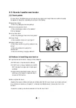
Page 78: ...witch to START position As soon as the engine starts release the key switch to ON position 7 Check if the battery charging indicator is OFF If not stop the engine immediately and check the problem 8 Run engine for a few minutes to allow engine oil and transmission oil to warm up 4 Operation and Work 4 1 Engine start and stop 1 Engine start Caution Check each part before starting the engine Check i...

Page 79: ...king brake 2 Place the range gear shift lever and HST forward reverse pedal in NEUTRAL and PTO switch in OFF 5 Wait until the cold start aid indicator is OFF about 10 seconds 4 Turn key switch to ON and check if the battery charging indicator and cold start aid indicator are ON 6 Turn key switch to START position As soon as the engine starts release the key switch to ON position 8 Run engine for a...

Page 80: ...tart stop and wait 1 2 minutes and then restart Place the PTO switch OFF when starting When the engine is turning do not turn the start key to START position It may cause the failure of start motor In cold weather carry out warming procedure If the machine is used in the state that the engine does not reach the normal temperature the engine life shall be reduced When storing the tractor in the col...

Page 81: ...wly with pressing throttle pedal slowly 4 2 How to drive and how to stop Release the clutch pedal slowly If not the transmission gear life shall be reduced and it may cause a sudden start Notice 1 How to drive Mechanical type Position control lever Main gear shift lever Range gear shift lever Parking brake lever Throttle pedal Brake pedals Shuttle lever Clutch pedal Throttle lever Cabin Position c...

Page 82: ...cruise control drive shall be stopped For HST model there is a switch on the driver s seat to control engine cut off for driver s safety If the operator leaves the driver s seat without safety measures the engine shall be stopped automatically For further information see section 2 When driving or working with a tractor operate it more than 1500 rev min Press the HST forward reverse pedal slowly If...

Page 83: ... z Just pressing the HST forward reverse pedal respectively makes it possible to travel forward and in reverse Moving forward reverse neutral and changing speed can be controlled by these pedals z The range gear shift lever must be operated in the neutral state of the pedal and after tractor has stopped completely z Set driving speed properly depending on the road condition HST forward pedal Throt...

Page 84: ...elease the HST forward reverse pedal and press the brake pedals immediately HST type 2 Pull throttle lever backward to decrease the engine speed and turn OFF the key switch Brake pedals Clutch pedal Throttle lever Key switch HST forward pedal Throttle lever HST reverse pedal Brake pedals Cabin Parking brake lever Parking brake lever is located in right hand side of the driver s station for cabin m...

Page 85: ...rake is not applied The tractor may roll Apply the parking brake at all times before leaving the tractor Remove the ignition key always after stopping engine Mechanical type Throttle lever Key switch PTO switch 1 Release the HST forward reverse pedal slowly and pull the throttle lever backward to reduce the engine speed and place the range gear shift lever in NEUTRAL and PTO switch to OFF 3 Apply ...

Page 86: ...mplements installed turn slowly by wide turning radius While traveling DO NOT ride your foot on the clutch pedal if fitted or brake pedal While traveling DO NOT operate any implement such as tiller loader etc Caution Position control lever 5 Driving tractor on the road z When facing downhill DO NOT place the gear lever in Neutral position z When driving the tractor on a unpaved road by attaching a...

Page 87: ...t for engine and all moving parts to stop z Have to apply the wheel chocks when parking the tractor on a slope unavoidably If it is necessary to park the tractor on a slope furthermore with loaded trailer the tractor may roll down even though the parking brake is applied In this case apply all the gears in lowest speed and apply chocks or blocks to all the tires Mechanical downward slope reverse 1...

Page 88: ...fter using first 50 hours Replace the engine oil filter and hydraulic oil filters after first 50 hours of work and check each part of your tractor as reference of chapter 5 Lubrication and Maintenance See section 5 4 in this manual If possible contact your authorized dealer for First 50 hour check z Appearance check Is there any damage while transporting z Engine cooling system check Is there anti...

Page 89: ... upper link of 3 point linkage If not it may cause tipping or turnover DO NOT connect the implements that require more power than can be generated by your tractor Never stand between implement and tractor when backing up z When attaching the implement comply with the followings 1 Set the implement upright on a level surface and approach the implement in reverse 2 Stop the tractor on attaching posi...

Page 90: ... lower part after adjusting z For upper link Lift up the lock spring to release the handle and turn the upper link by using the handle Apply the lock spring after adjusting Lift rod LH Lift rod RH Upper link Lift rod handle Adjustment of stabilizer s length ⓐ Check chain type z Turn the knob 2 to adjust the length of the stabilizer 1 After the adjustment let it tightened firmly by fixing nut 1 Whe...

Page 91: ...in into the desired hole and let it tightened firmly by locking spring When adjusting the stabilizer s length adjust the implement s swinging clearance to be 20 40mm 0 79 1 57 in left and right Notice Telescopic stabilizer 19 0 74 A B C Max G H J L N CAT 1 19 3 0 75 683 26 8 12 0 47 39 1 53 35 1 53 22 4 0 88 22 0 86 44 5 1 75 69 2 71 76 2 99 44 1 73 Unit mm unit inch D Min K E Max F Min ...

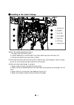
Page 92: ...int linkage to maximum height and fix it by turning the down speed control knob to lock position z When removing 3 point linkage if necessary 1 Remove upper link pin 7 and detach the upper link 5 2 Detach rear side of the stabilizer 2 from the lower link 3 while holding lower link tightly not to fall down 3 Remove lift rod LH lift rod RH and stabilizer 2 step by step 4 Remove lower link 3 carefull...

Page 93: ...shield is removed or damaged replace it with a new one z Suitable Clothes Protect Entanglement When checking or attaching implement to the PTO shaft wear tight fitting clothes and safety equipment instead of loose or long clothes Also slippers high heel shoes are not suitable Wear the suitable clothes Warning Do not approach the rotating shaft such as PTO shaft or cooling fan especially with loose...

Page 94: ...off drive shafts refer to the drawings as below z After installing implements check the inclination of the drive shaft and interference with PTO safety cover and other structure The stiff inclination of the drive shaft make a loud noise and may cause a failure of the driveline ...

Page 95: ...ertical load 400kg when pulled 882 lbs 575kg when pushed 1268 lbs z Horizontal load 2800kg 6173 lbs Pulling from the tractor rear axle or any point above the axle may cause the tractor to overturn Use always the drawbar or hitch for pulling work Do not tow equipment without brakes weighing more than twice the tractor weight When locking the hitch or drawbar with pin after aligning to the towing eq...

Page 96: ...m the rear of the tractor are as follows z EC Version Pin No Function 1 Left turn signal light 2 NA 3 Ground Earth 4 Right turn signal light 5 Side light 6 Brake light 7 Side light z ASAE Version Pin No Function 1 Ground Earth 2 Working light 3 Left turn signal light 4 Brake light 5 Right turn signal light 6 License number plate light 7 Auxiliary 7 Pole Connector EC 7 Pole Connector ASAE ...

Page 97: ...ll models Remarks Technically total maximum permissible mass 3008kg 6631 lb It depends on the load capacity of the tires See next page Front axle 1320kg 2910 lb Rear axle 2105kg 4641 lb Maximum permissible mass is measured with only the front or rear wheels on the scales inclusive of ballasts and with mounted equipments in the raised position Do not exceed the maximum permissible mass above and or...

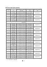
Page 98: ... 6 160 KPa 23 2 psi 1600 3527 lb 3008 6631 lb 2 360 70R24 1 6 160 KPa 23 2 psi 3000 6614 lb 1 280 70R16 2 4 240 KPa 34 8 psi 2240 4938 lb 3008 6631 lb 2 380 70R24 1 6 160 KPa 23 2 psi 3300 7275 lb 1 250 80R16 1 6 160 KPa 23 2 psi 1600 3527 lb 3008 6631 lb 2 380 70R24 1 6 160 KPa 23 2 psi 3300 7275 lb 1 240 70R16 2 4 240 KPa 34 8 psi 1800 3968 lb 3008 6631 lb 2 380 70R20 1 6 160 KPa 23 2 psi 3000 6...

Page 99: ...g rear wheel track check the radial and lateral clearance between rear tire and tractor chassis as below A 60mm 2 4 in Minimum B 50mm 2 0 in Minimum z Depending on rim or disk type the front and rear wheel tracks may vary A B Front wheel track 9 5 16 with rim disk W8x16 Rear wheel track 13 6 24 with rim disk W10x24 When adjusting the wheel track pay attention to the direction of tire lugs if it sh...

Page 100: ...4 23 Rear wheel track 13 6 24 with rim disk W10x24 Unit mm inch 1266 49 8in N A N A N A N A N A N A N A ...

Page 101: ...nd the tractor z DO NOT allow to stay people under the front end loader z DO NOT allow people on the bucket z Only install a front end loader with a parallel guidance system and use it all the time this system will ensure that the load in the bucket will remain horizontal regardless of the height of the lifting booms After using the front end loader lock the joystick lever to prevent the accident ...

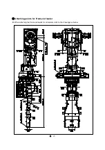
Page 102: ...4 25 Attaching points for Front end loader z When attaching the front end loader for all models refer to the drawings as below ...

Page 103: ...es to be contacted with the cast Check all the possible interferences by combinations of the steering and oscillation of the front axle 5 Tighten the locking nuts of the each side 9 Adjusting Steering angle z If the front wheel track is adjusted or front tires are replaced with new tires having bigger diameter or width or one of the front equipments is attached the steering angle must be adjusted ...

Page 104: ...1 Front loader Max lift capacity Bucket pivot point 1197 kg 2638 9 lb 1197 kg 2638 9 lb 2 Rotavator Max tilling width 1800 mm 70 9 in 1800 mm 70 9 in 3 Backhoe Max digging depth 2280 mm 89 8 in 2280 mm 89 8 in 4 Rotary cutter Max working width 2134 mm 84 0 in 2134 mm 84 0 in 5 Mid mower Max working width 1829 mm 72 0 in 1829 mm 72 0 in 6 Landscape lake Max working width 1829 mm 72 0 in 1829 mm 72 ...

Page 105: ...iscarded filters must not be thrown away Take disposed filters to authorized collection points Cleaning the cabin inside z Protective clothing worn when handling the sprayer with pesticides or when carrying out external works must be removed and stored away carefully before re entering the cabin z After working with pesticides ventilate the cabin and clean the inside parts interior trim panels ste...

Page 106: ...13 4 85 6 50 9 01 10 7 12 6 16 8 Reverse 1 02 1 20 1 42 1 90 2 30 2 73 3 20 4 29 5 08 6 03 7 08 9 49 13 2 15 6 18 3 24 6 mph 0 63 0 75 0 88 1 18 1 43 1 69 1 99 2 67 3 16 3 75 4 40 5 90 8 17 9 69 11 4 15 3 Range gear 1 2 3 4 Main gear 1 2 3 4 1 2 3 4 1 2 3 4 1 2 3 4 Forward 0 18 0 22 0 25 0 34 0 41 0 49 0 58 0 77 0 91 1 08 1 27 1 71 2 36 2 80 3 30 4 41 mph 0 11 0 13 0 16 0 21 0 26 0 30 0 36 0 48 0 ...

Page 107: ...speed unit Km h Mile h Range gear 1 2 3 Forward 0 4 92 0 3 06 0 11 2 0 6 98 0 25 7 0 16 0 Reverse 0 4 92 0 3 06 0 11 2 0 6 98 0 25 7 0 16 0 XR4040H XR4046H Note Engine rated speed 2600 rev min Dynamic load radius 578mm 22 8 in ...

Page 108: ...nance z The jacking points for maintenance is depending on serviced parts case by case Do not hesitate to contact your authorized dealer for asking z Do not use the front axle assembly or steering linkage and cylinder for jacking point These components have some rotating pivots and or does not have enough structural strength z For general maintenance use flat surface under the engine frame end or ...

Page 109: ...5 2 5 2 Maintenance chart 8 9 14 3 4 11 12 13 19 17 7 6 5 23 10 15 2 22 1 18 21 16 20 26 25 24 Mechanical type ...

Page 110: ...tery 5 17 9 Engine belt tension 5 21 10 Valve clearance 5 24 11 Nozzle injection pressure 5 24 12 Hydraulic oil filter 5 7 5 20 13 Transmission oil 5 17 5 23 14 Front axle oil 5 17 5 23 15 Steering cylinder 5 16 16 Front axle holder Steering arm 5 16 17 3 Point linkage 5 16 18 Clutch pedal play 5 14 19 Brake pedal play 5 14 20 Turn signal lights Lights Horn 5 11 21 Instrument panel Indicators 5 10...

Page 111: ...5 4 8 9 14 3 4 11 12 13 18 17 7 6 5 23 10 15 2 22 1 19 21 16 20 26 25 24 HST type ...

Page 112: ...y 5 17 9 Engine belt tension 5 21 10 Valve clearance 5 24 11 Nozzle injection pressure 5 24 12 Hydraulic oil filter 5 7 5 20 13 Transmission oil 5 17 5 23 14 Front axle oil 5 17 5 23 15 Steering cylinder 5 16 16 Front axle holder Steering arm 5 16 17 3 Point linkage 5 16 18 HST Pedal Neutral state 5 15 19 Brake pedal play 5 14 20 Turn signal lights Lights Horn 5 11 21 Instrument panel Indicators 5...

Page 113: ...8 LSTH570 Manufacturer GS Caltex or S OIL TOTAL Co Ltd Front axle oil 8 L 2 1 U S gals API GL4 SAE 80W EPK 80W90 Manufacturer S OIL TOTAL Co Ltd Grease Front axle holder Steering cylinder pin 3 point linkage etc Proper amount NLGI 2 RECOMMENDED OIL VISCOSITIES The correct engine oil viscosity grade is dependent upon ambient temperature Refer to the chart below when selecting oil for your tractor e...

Page 114: ...ue of exhaust manifold bolts Check and adjust V belts and tension Tighten all cooling system hose connections Check torque of safety cab or frame mounting bolts Check torque of front end weight clamp bolts Where fitted Check torque of wheel bolts and nuts Check tire pressures and condition Clean radiator oil cooler and A C condenser cores Where fitted Check radiator coolant level and specific grav...

Page 115: ...Drain water from Fuel filter 1 Loosen the drain plug and drain water inside of the filter Approx 150cc 9 1 in 2 Tighten the drain plug and bleed the air from the fuel filter See page 5 27 Fuel filter warning indicator Main fuel filter Drain plug ...

Page 116: ... Condition of air cleaner primary element z Checking oil level Check oil level before starting engine or at 5 minutes later after stopping engine Check If the oil is between MAX and MIN mark of the oil gauge If necessary add new oil It must only be performed while the engine is stopped 1 Engine oil z Oil capacity 5 7 L 1 5 U S gals z Using Engine oil Diesel engine oil API CJ 4 Select engine oil ac...

Page 117: ... fuel tank with fuel z Capacity 45L 11 9 U S gals If the engine stops after finishing work fill the tank fully As the temperature drops down the humidity in the fuel tank is condensed and may mix with the fuel Notice 3 Instrument panel Indicators z Check if instrument panel and its indicators are normally turned on off before starting engine or while operating engine periodically z Engine oil pres...

Page 118: ...Turn signal lights Lights and Horn z Check the operation status of light turn signal lights horn etc Use the bulb of rated capacity In case of using the improper bulb it may cause a failure of electric system Notice Horn switch Turn signal light switch Light switch z If the light is OFF suddenly when operating the switch check the problems as followings 1 Check the relating fuse in the fuse box 2 ...

Page 119: ...e evacuator valve placed downward Do not start the engine or close the hood if the filter element is not assembled Notice z If the dust is not removed by tapping use compressed air less than 500kPa 5bar 72psi from inside to outside as shown in the right figure to remove the dust and foreign materials And clean inside the filter element with a clean damp cloth Do not tap the element on a hard place...

Page 120: ...the tire arbitrarily Carry out the work in the tire repair center equipped with a expert and special safety tools When checking tire pressures keep the body away from the valve mechanism or cap The tire pressures vary depending on the load weighing on the axles Caution 8 Tire air pressure and damage Check z Check the air pressure or the damage of the tires daily Always use the correct pressure for...

Page 121: ...rake pedal Adjuster Locking nut 11 Adjustment of Brake pedal play z Normal distance 50 60mm 1 96 2 36 in If the pedal play distance is over 60mm 2 36 in adjust it as below 1 Loosen the locking nut and turn brake rod to adjust 2 If brake rod is tightened the pedal play shall be reduced and if brake rod is loosened it shall be increased 3 After adjusting the pedal play tighten the locking nut 4 Chec...

Page 122: ...2WD and apply the wheel chock to the front wheels It is necessary for the tractor not to move when the engine starts 4 After loosening bolt 1 in half adjust the height of forward pedal and reverse pedal to be same by turning shaft 2 to the left right little by little After adjusting tighten the bolt 1 5 Start the engine after checking that HST neutral switch is pressed by the linkage When lifting ...

Page 123: ...ipple z Steering cylinder pins LH RH z Front axle holder Steering arm LH RH z 3 point linkage 5 7 Every 50 hour check Grease nipple Grease nipple Grease nipple Grease nipple 2 Cleaning Radiator and Radiator screen z See page 5 13 ...

Page 124: ... cracked charred twisted soft or loose covered hoses and fittings z Before removing hydraulic components make sure to check that hydraulic pressure is relieved completely The leaks of pressurized oil can cause a fatal physical injury For further information refer to the section 3 5 Hydraulic system in this manual 3 Checking Transmission oil z Stop the tractor on level surface and apply the Parking...

Page 125: ...r Blow the dust from the upper surface through the element to the underside Hold the nozzle at least 12 in 300mm from the element to prevent damage to the filter media z Clean all filter chambers with a damp lint free cloth Re install the filter elements z Re install the filter cover and tighten the bolts The filters are made of specially treated media with a rubber sealing strip bonded around the...

Page 126: ...city at the end of this manual or See page5 6 z Check any leakage of the engine while running the engine for several minutes at idle rpm z Stop the engine After about 5 10 minutes later check again if the oil level is between MIN and MAX mark z Install the oil gauge Replace Engine oil filter z Clean carefully around the filter z Coat clean engine oil on the packing of new filter and check the pack...

Page 127: ...on level surface and apply parking brake and lower implements and stop the engine z Carefully clean around the filter and set a clean container under the filter z Coat clean hydraulic oil on the packing of new filter and check the packing is placed well in the groove z Turn the oil filter CCW to remove with filter wrench z Turn the new filter CW to assemble until the packing makes contact with the...

Page 128: ...ension of fan belt exceeds the standard value loosen the bolt and adjust the tension Belt tension crank shaft pulley alternator pulley Normal approx 5mm 0 2 in if pressed by 50N 11 2 lb z When adjusting the tension 1 Loosen 2 bolts of alternator and insert the bar between crank case and pull the bar to apply tension to the belt 2 With proper tension tighten the bolts attached to the adjusting plat...

Page 129: ...the filter element by pushing it deeply into the filter housing z Remove the dust of the evacuator valve and clean the inside of the cover z Assemble the cover with the evacuator valve placed downward Do not start the engine or close the hood if the filter element is not assembled Notice Cover Primary element Evacuator valve Safety filter element 5 Toe in z Check and adjust Toe in of the front whe...

Page 130: ...s 2 Changing Transmission oil z Stop tractor on a level surface and apply parking brake Run engine for several minutes to warm oil and lower implements and stop the engine z Set container under drain plugs and remove the drain plugs under the transmission and drain oil completely z Clean metal sludge stuck to drain plugs and tighten the drain plugs again with copper washer z Add new oil until the ...

Page 131: ...Close Open 4 Adjusting Engine valve clearance z Ask your authorized dealer to check the valve clearance Normal 0 2mm 0 0079 in If the gap is large valves makes a loud tapping noise and if the gap is too small it is hard to compress by which the engine output falls down or burns a valve 5 Checking Nozzle injection pressure z Contact your authorized dealer for check Normal injection pressure XR4040 ...

Page 132: ...r element as shown in the right figure z Clean both filter chambers with a damp lint free cloth z Replace the cabin air filters with a new one z Re install the filter cover and tighten the bolts The filters are made of specially treated media with a rubber sealing strip bonded around the sides Take care not to damage the element during installation Notice Cabin air filters Bolt Filter cover ...

Page 133: ... time Drain port Radiator drain cock Engine engine coolant drain plug z Run the engine for 5 minutes after injecting the anti freeze to mix it with water well Warning When opening the radiator cap be careful of the escaping hot water or steam Cool down the coolant sufficiently before opening Drainage cock Add coolant z Supply the clean soft water to the coolant If not the radiator shall be corrode...

Page 134: ... from fuel system Fuel system z After replacing fuel pre filter or fuel filter bleed air in the fuel system 1 Turn key switch ON position 2 Press down manual pump several times in the right figure 3 Press down manual pump in the right figure several times to fill the fuel system with fuel The air shall bleed out from fuel system Manual pump Fuel filter Fuel feed pump Fuel pre filter Burner When ch...

Page 135: ...r injury Notice Fuse check and replacement z How to change the fuse 1 Remove the cover of fuse box 2 Check each fuse and remove the damaged fuse 3 Change with new one same as damaged one z Chassis fuse box is located under the front console and cabin fuse box is on the left cabin pillar z The capacity and function of each fuse is described on the fuse box cover Cabin fuse box Cabin type 2 Fuse Mai...

Page 136: ... necessary replace it with a genuine part Rated capacity 100 A z As the main fuse is a device to protect electric system and wirings if damaged check if there is a trouble in the electric system Contact your authorized dealer for check Battery cable Main fuse for cabin z Main fuse for cabin is attached to the right side of the engine z Remove the cover from the fuse box and pull out the main fuse ...

Page 137: ...Caution The gas generated from the battery is explosive comply with following instructions Keep cigarettes sparks and flames away from battery Use a flashlight to check battery electrolyte level or indicator Never check battery charge by placing a metal object across the terminals Use a voltmeter or hydrometer Always remove grounded battery clamp first and assemble it last If not It can cause expl...

Page 138: ...and apply parking brake and remove the ignition key before replacing the battery Put on eye protection and globes to protect human body from poisonous sulfuric acid before handling the battery Always remove grounded battery clamp first and assemble it last If not It can cause an explosion by spark Keep all flames and sparks away and DO NOT smoke while you charge the battery Replaced old battery mu...

Page 139: ...ectrolyte during the charging 7 Unplug charge cord and remove charger cables 8 Attach battery to the tractor Put on eye protection and globes to protect human body from poisonous sulfuric acid before handling the battery Always remove grounded battery clamp first and assemble it last If not It can cause explosion by spark Keep all flames and sparks away and DO NOT smoke while you charge battery De...

Page 140: ...s and sparks away and DO NOT smoke while handling the battery How to use jumper cables if the battery which is attached to the tractor is discharged and needs to connect a auxiliary battery follow the instructions as below Connecting order of jumper cables Engine Normal Discharge Red cable Black cable ⓐ Connecting Jumper cables z Check followings before connecting the cables is the spring of clamp...

Page 141: ... start motor turns but the engine does not start The battery is weak bad ground Improper viscosity of engine oil Air in fuel system Fuel filter clogged Error in engine body Fuel cock closed Charge or replace Tighten the ground Replace the oil with proper viscosity Bleed the air Wash or replace the filter Repair Open the cock Engine revolution is irregular Air in fuel system Fuel filter clogged Inj...

Page 142: ...rbon piled to valve seat Bad adjustment of valve gap Bad injection timing Lack of fuel supply Air cleaner clogged Repair Repair Repair Repair Check fuel system Clean or replace Engine oil pressure indicator is ON during operation Lack of engine oil Low viscosity of engine oil Warning light switch error Fault of oil pump Oil filter element is clogged Supplement Replace the proper oil viscosity Repl...

Page 143: ...ulic pump failure Control valve failure Cylinder or cylinder related parts broken Aid oil Tighten the filter or replace seal of connecting parts Clean the filter or replace Repair or replace Repair or replace Repair or replace Oil leakage Connecting part loosened Oil seal damaged Pipe cracked Tighten Replace Replace If lever is placed on the raising position and relief valve sound off Upper limit ...

Page 144: ...ilure Relief valve Valve spool clogged Setting pressure too low Check mounted condition of steering unit and column Replace Apply regular torque Adjust RPM or Repair Repair or replace Repair or replace Reset or adjust Cylinder does not work smoothly as steering wheel movement Air in steering line if not used for a long time Air in suction pipe Piston seal damaged Bleed air Repair Replace Steering ...

Page 145: ... and repair Headlight does not ON Light bulb cut off Fuse blown Replace Check the cause and replace Horn does not sound Switch failure Abnormal wiring Horn failure Replace Repair Replace Turn signal Light does not work Light bulb cut off Bad connection Fuse blown Replace Tighten terminals Check the cause and replace it Cold start aid indicator does not ON option Relay or timer damaged Bad connecti...

Page 146: ...it Heater hose Compressor Cooler hose Quick coupler Maintenance of the air conditioning system components Compressor Receiver drier Condenser Heater evaporator unit and connection parts must be performed in the designated dealer DO NOT disassemble the components arbitrary Caution Condenser w receiver drier ...

Page 147: ...or selecting warm or cool air Turn the switch clockwise blue for cool air and otherwise turn it counter clockwise red Air conditioner switch Blower control switch Heater control switch Direction control switch 2 Air direction control z To control the air direction adjust the blade angle of the blower outlets z For internal circulation move the ventilation lever to the internal circulation position...

Page 148: ...brush or low pressurized air or water z Pay attention that the cooling fin does not damaged If necessary repair the distortion of fin 4 Belt tension adjustment z Check the belt tension is proper and If necessary adjust the tension by compressor adjusting bolt z Tension approx 10 mm 0 4 in when pressed by 98N 22 lbf z Check the damaged part of the belt and if necessary after checking the pulley ali...

Page 149: ...ck the abnormal noise sounds and If necessary contact your authorized dealer for check 2 Control switch check z Check the electric switches of the control panel is normally operated If there is a trouble on air conditioning system DO NOT disassemble the components arbitrary contact your authorized dealer for check Caution ...

Page 150: ...oning is insufficient despite of the normal operation of compressor and blower Low and high pressure is low Leakage of refrigerant Contact the dealer Low and high pressure is high Refrigerant overcharged Contact the dealer Condenser or radiator screen was clogged Clean condenser and the screen Air is in air conditioning line Contact the dealer Expansion valve does not control the refrigerant flow ...

Page 151: ...nt Coil of magnet clutch was shorted or cut off Contact the dealer Compressor failure Contact the dealer Wiring cut off or poor connection such as ground Check and repair 5 The warm airflow does not blow The amount of warm water is small Check and add the engine coolant Heater line is clogged or distorted Check and repair Poor operation of the thermostat of engine coolant Repair or replace ...

Page 152: ...System diagram Heater evaporator Fan motor Evaporator core Heater core Hot water Control panel Engine Compressor Fan Radiator Condenser Quick coupler Receiver dryer Heater lose Cooler hose Line Expansion valve ...

Page 153: ...7 1 Unit mm 7 Dimension and Specification Cabin type ...

Page 154: ...7 2 Unit mm Roll bar type ...

Page 155: ...1 Engine speed 1000 2800 rpm Maximum torque 130 N m 1600 rpm 139 N m 1600 rpm Rated power 30 kW 2600 rpm 34 kW 2600 rpm FUEL INJECTION SYSTEM Type Mechanical PFR Fuel filter Replaceable cartridge type Injection order 1 3 4 2 LUBRICATION SYSTEM Type Forced circulation Pump Trochoid gear pump Filter Replaceable cartridge type COOLING SYSTEM Pump Centrifugal type Temperature control Thermostat Air cl...

Page 156: ...n speed control valve Pump Gear pump type Engine drive Rated flow 31 2LPM 8 2GPM System pressure 17MPa 2466psi Lift capacity Lower link end 1250 kgf 2756 lbf 24 behind lift point 1120 kgf 2469 lbf REMOTE CONTROL Type Double acting Spring return type Detent type optional No of Q coupler 4EA optional 2 or 6EA F Loader coupler Front outlet valve Joystick loader valve optional STEERING SYSTEM Type Hyd...

Page 157: ...2V 5W Cabin Turn signal lights rear 12V 21W Stop light Taillight rear 12V 21W 5W Work lights 12V 27W Grille 37 5W Cabin 27W Roll bar Indoor light 12V 10W Cabin only Instrument indicator lights LED Cold start aid Glow plug STD AGRI TIRE Front 9 5 16 6PR Rear 13 6 24 8PR WHEEL TRACK ADJUSTMENT Front Tracks N A Dimension N A Rear Tracks N A Dimension N A These specifications are only general product ...

Page 158: ...LSTH570 Manufacturer GS Caltex or S OIL TOTAL Co Ltd Front axle oil 8 L 2 1 U S gals API GL4 SAE 80W EPK 80W90 Manufacturer S OIL TOTAL Co Ltd Grease Front axle holder Steering cylinder pin 3 point linkage etc Proper amount NLGI 2 RECOMMENDED OIL VISCOSITIES The correct engine oil viscosity grade is dependent upon ambient temperature Refer to the chart below when selecting oil for your tractor eng...

Reviews: