


I185 GB 06 15
LRX D01
99
IO LINK FUNCTION
Hardware Configuration:
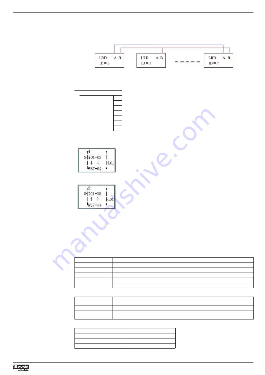
1. Link LRD as show below.
2. Set the LRD in SET menu to No Remote IO.
3. Set those LRD’s ID continuously 00 ,01,02,… The max number of the ID is 07.
Example:
1. Link 8 20 pointe V type LRD according to the steps as show above.
2. Create a program as show below in those 8 LRD.
L 01
I01
M01
M02
M03
M04
M05
M06
M07
M08
3. Set L01 of the LRD which’s ID =7 as fellow illustration.
4. L01 of other 7 LRD be set as fellow illustration.
5. Run program. Let I01 of the LRD which’s ID = 7 on. And M01~M08 will be on state.
6. You will find M01~M08 of other 7 LRD will be controlled by the M01~M08 of the LRD which’s ID=7.
MODBUS RTU MASTER
There are 15 MODBUS functions: MU01~MU0F. Remote IO and Date Link are precedence. The master mode is executed when the system setting
is NO Remote IO and ID isn’t 0.
There can be a number of communication orders in one program, but only one order can come into possession of communication port at the
same time.
Communication function codes:
The coil used in MODBUS function:
Received (M3D)
M3D is set to ON after received, then check-up for error
Transferring data to target address if there is no error
Error flag (M3E)
Communication error flag
Time out flag (M3F)
M3F is set to 1 when the time from after sending to start receiving is longer than setting, and M3D also be
set to 1. M3F is automatically reset if M3D reset
Mode
Communication function code
1
03 (read register)
2
06 (write single register)
3
10 (write some registers)
4
01 (read coil)
5
05 (write single coil)
The time out time is depending communication baud rate as shown in the table below:
BBaud rate (bps)
Time (ms)
4800
9600
19200
38400
125
57600
100
115200
80