background image

The RS232 / Alarm input allows you to control the Multiplexer system from your PC. In order to achieve 
this, you will require an RS232 COM Port communication program installed on your PC. There are many of 
these software programs available on the internet, some of which are free.

The remote connection on the Multiplexer uses 8 data bits, 1 start bit, and 1 stop bit. 
Below is an example of the data stream with the control codes shown. 

The PC keyboard simulates the Quad Processor’s keypad. For example, pressing “z” will make the 
Multiplexer go to Zoom mode. Note that the letters are case sensitive. Below is a list of corresponding keys, 
and their codes:

11

RS232 REMOTE PROTOCOL

MENU

0x4D

M

14

0x45

E

ESC

0x1B

ESC

15

0x46

F

FREEZE

0x5A

Z

16

0x47

G

LIVE

0x49

I

ENTER+FREEZE

0x48

H

VCR

0x56

V

ENTER+LIVE

0x4A

J

ZOOM

0x7A

z

ENTER+VCR

0x4F

O

PIP

0x50

P

ENTER

0x0D

ENTER

LEFT

0x4C

L

SEQUENCE 1

0x61

a

RIGHT

0x52

R

SEQUENCE 2

0x62

b

UP

0x55

U

SEQUENCE 3

0x63

c

DOWN

0x4E

N

SEQUENCE 4

0x64

d

KEY_LOCK

0x4B

K

SEQUENCE 5

0x65

e

1

0x31

1

SEQUENCE 6

0x66

f

2

0x32

2

SEQUENCE 7

0x67

g

3

0x33

3

SEQUENCE 8

0x68

h

4

0x34

4

SEQUENCE 9

0x69

i

5

0x35

5

SEQUENCE 10

0x6A

j

6

0x36

6

SEQUENCE 11

0x6B

k

7

0x37

7

SEQUENCE 12

0x6C

l

8

0x38

8

SEQUENCE 13

0x6D

m

9

0x39

9

SEQUENCE 14

0x6E

n

10

0x41

A

SEQUENCE 15

0x6F

o

11

0x42

B

SEQUENCE 15

0x6F

o

12

0x43

C

SEQUENCE 16

0x70

p

13

0x44

D

ACT – OxFF

OxCO

ID

FUNCTION

STOP – Ox7F

FUNCTION

CODE

KEY

FUNCTION

CODE

KEY

Summary of Contents for SGX1600

Page 1: ...HANNEL COLOR MULTIPLEXER Model SGX1600 Please be sure to read carefully and follow all the safety information Keep the manual in a safe place for future reference www strategicvista com Instruction Ma...

Page 2: ...ther products available please visit our website at www strategicvista com FEATURES 16 Channel Color Multiplexer Features Full Duplex Multiplexing 16 cameras can record playback display live video at...

Page 3: ...yourself Refer all servicing to qualified service personnel This unit should be operated only from the type of power source indicated on the manufacturer s label This installation should conform to al...

Page 4: ...TOCOL 11 MOTION DETECTION 12 TROUBLESHOOTING 13 TECHNICAL SPECIFICATIONS 14 OPTIONAL ACCESSORIES 15 APPENDIX 1 TYPICAL CONFIGURATION 16 APPENDIX 2 CONNECTION TO A PIR MOTION SENSOR 17 APPENDIX 3 CONNE...

Page 5: ...nu a ENTER Selects Menu options to be edited in Menu mode Initiates and stops Auto Sequencing refer to page 10 for more details b ESC Confirms changes to options in Menu mode Exits Menu mode and vario...

Page 6: ...cture The miniature picture has a size white outline depicting which section of the camera view is being zoomed in on You can press the arrow keys to move the Zoom area To change between Full Screen c...

Page 7: ...g the subscreen via the arrow keys is possible VCR button shows that you can swap screens to view VCR playback in PIP mode LIVE button shows that you can swap screens to view other channels in PIP mod...

Page 8: ...n screen for the duration of the Event When Message Latch in OFF the icons only appear for only the programmed Alarm Duration Security Lock Activates Deactivates the Lock feature which when turned ON...

Page 9: ...The EVENT option will record for more time on the channel in which the alarm was triggered For example if an alarm is triggered on Channel 1 Event recording will follow this channel sequence 1 2 1 3...

Page 10: ...hannel where the Alarm is taking place If two channels have alarms simultaneously the Call monitor will display those two channels sequencing in Full Screen viewing SVHS OUT Connect this output port t...

Page 11: ...uto Sequencing in the Subscreen You can swap to enable Sequencing to occur in the Main screen by pressing ENTER and the Channel currently shown in the Main screen simultaneously In Quad mode pressing...

Page 12: ...sponding keys and their codes 11 RS232 REMOTE PROTOCOL MENU 0x4D M 14 0x45 E ESC 0x1B ESC 15 0x46 F FREEZE 0x5A Z 16 0x47 G LIVE 0x49 I ENTER FREEZE 0x48 H VCR 0x56 V ENTER LIVE 0x4A J ZOOM 0x7A z ENT...

Page 13: ...ate between each target using the arrow keys and use the following keys MOTION turns the target area ON OFF ON OFF Camera 1 15 toggles the corresponding target on the cursor line ON or OFF Since there...

Page 14: ...signs and specifications without notice and without incurring any obligations E O E Cam era Inputs 16 Channel BNC VCR Input 1 BNC 1 S VIDEO Cam era Loop Back 16 Channel BNC Main Monitor Output 1 Vp p...

Page 15: ...om a 40 hour real time or 960 Hour time lapse VCR TO ORDER THESE ACCESSORY ITEMS OR FOR A COMPLETE LINE OF ACCESSORIES www strategicvista com SPECIALTY CAMERAS Rotates camera up to 270 NIGHTVISION Wea...

Page 16: ...ll Monitor Record Play 1 Main Monitor GND VCR PC RS232 RS232 PC Alarm Input Sensor Alarm YOU CAN ALSO CONNECT TWO MONITORS USING THE CONFIGURATION SHOWN BELOW THE 16 CH MULTIPLEXER HAS BNC JACKS TO CO...

Page 17: ...ach PIR Sensor connects via 2 wires 1 to a specific Channel and the other to the Ground input Another Ground input is available on the bottom right of the back panel of the Multiplexer The diagram bel...

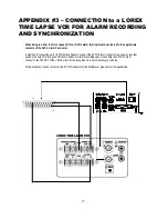
Page 18: ...onnector In addition to connecting up to 16 PIR Motion Sensors connect the 25 Pin Alarm Connector to a security recorder such as the Lorex Time Lapse VCR shown below for Alarm Recording upon motion de...

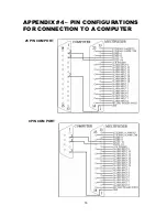
Page 19: ...APPENDIX 4 PIN CONFIGURATIONS FOR CONNECTION TO A COMPUTER 25 PIN COM PORT 9 PIN COM PORT 18...

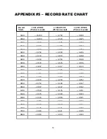
Page 20: ...036H 1 667 0 417 0 104 040H 1 500 0 375 0 094 048H 1 250 0 313 0 078 060H 1 000 0 250 0 063 072H 0 833 0 208 0 052 080H 0 750 0 188 0 047 084H 0 667 0 167 0 042 120H 0 500 0 125 0 031 160H 0 375 0 09...

Reviews: