background image

10

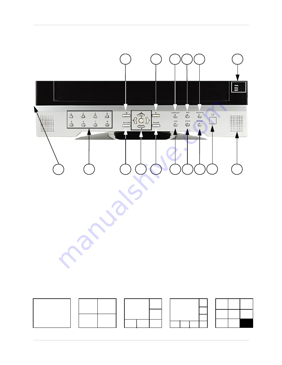
Front Panel 

Front Panel

1. 

REW BUTTON

 - Reverses the playback of the currently displayed Video 

2. 

FF BUTTON - 

Fast forwards the playback of the currently displayed Video

3. 

DISPLAY 

- Changes the onscreen Camera display:

• Single - Displays a single camera onscreen

• Quad - Displays 4 cameras onscreen

• 6 Camera Display - Displays 6 cameras onscreen. One main camera is displayed in the top 

left corner, and 5 other cameras frame the bottom and right side.

• 8 Camera Display - Displays 8 cameras onscreen. One main camera is displayed in the top 

left corner, and 7 other cameras frame the bottom and right side. 

• 8 Camera Display(2) - Displays 8 cameras onscreen in a grid pattern.

1

2

3

4

5

6

8

9

10

11

12

13

14

15

16

7

SINGLE

QUAD

6 CAM

8 CAM

8 CAM (2)

Summary of Contents for SG17LD800

Page 1: ...cctv com LCD MONITOR 8 CHANNEL DVR COMBO Instruction Manual English Version 3 0 SERIES SG17LD800 SG19LD800 Series Includes SG17LD800 SG19LD800 Series NTSC SG17LD800P SG19LD800P Series PAL SG17LD804 16...

Page 2: ...OCK MATCH WIDE BLADE OF PLUG TO WIDE SLOT FULLY INSERT Thank you for purchasing the LCD 8 Channel DVR Combo Lorex is committed to providing our customers with a high quality reliable security product...

Page 3: ...cord and if its appearance indicates damage or deteriorated insulation have it replaced by your service technician 7 Power Cord Protection Power supply cords should be routed so that they are not like...

Page 4: ...can prevent fire electric shock or other hazards 16 Safety Check Upon completion of any service or repairs to this video product ask the service technician to perform safety checks recommended by the...

Page 5: ...ted z Consult the dealer or an experienced radio or television technician for assistance LOREX TECHNOLOGY INC http www lorexcctv com NOTE This equipment has been certified and found to comply with the...

Page 6: ...ntrol your DVR from any internet connected PC with Internet Explorer does not require Lorex Client software Universal Camera Inputs Supports Lorex proprietary 6 PIN DIN or any professional grade camer...

Page 7: ...Menu Navigation Controls Tips 27 System Setup Controls 28 Main Menu Options 28 Display Menu 29 33 OSD Onscreen Display 29 MONITOR 30 SEQUENCE 31 SEQUENCE SETUP MODE 32 SPOT OUT 33 SCREENSAVER 33 Came...

Page 8: ...ations 67 Storage Specifications 67 Alarm Specifications 68 Audio Specifications 68 Recording Specifications 68 Network Specifications 69 System Specifications 69 MC7520 Camera Specifications Appendix...

Page 9: ...YOUR PACKAGE TO CONFIRM THAT YOU HAVE RECEIVED THE COMPLETE SYSTEM INCLUDING ALL COMPONENTS SHOWN ABOVE REMOTE CONTROL ETHERNET CABLE 4 x 100 FT 30M EXTENSION CABLES 4 x CAMERAS WITH STANDS POWER ADAP...

Page 10: ...isplays 4 cameras onscreen 6 Camera Display Displays 6 cameras onscreen One main camera is displayed in the top left corner and 5 other cameras frame the bottom and right side 8 Camera Display Display...

Page 11: ...ras 5 SEARCH BUTTON Opens the Search Menu to view previously recorded data Refer to page 25 for detailed search options 6 SYSTEM LEDs Indicates the system status PWR Indicates that the system is ON OF...

Page 12: ...u Setup when in the Main Menu screen Exits from Search and PTZ Modes 10 PLAYBACK NAVIGATION CONTROLS Controls the playback of video Play Pause Fast Forward Rewind and controls the viewing area in PTZ...

Page 13: ...ive Use the Navigation Buttons keys to move the area being captured in ZOOM MODE To exit ZOOM MODE press the RETURN button 14 SETUP BUTTON Press to access the Main Menu Setup features Refer to page 28...

Page 14: ...draw power from the System additional power adapters are not needed 2 RCA AUDIO INPUTS Channel 1 4 Audio inputs for BNC type cameras with standard RCA Audio output 3 BNC VIDEO INPUTS Channel 1 8 came...

Page 15: ...page 73 for Alarm Block Configuration 7 PTZ CAMERA TERMINALS These terminals are used to control PTZ Pan Tilt Zoom type cameras Refer to page 74 for PTZ Configuration 8 ETHERNET PORT Located on the b...

Page 16: ...TON Enters the Search Menu ZOOM Zooms in on the current image NAVIGATION AND PLAYBACK Controls the playback of video Navigates in MENU and SEARCH mode Adjusts the zoomed area in ZOOM mode NOTE All But...

Page 17: ...low light conditions INPUT CABLE Connects Video Audio Power from the System STAND Stand connects to the Camera for mounting to walls ceilings and other surfaces INFRA RED LEDs Provides illumination f...

Page 18: ...you plan to install the camera in a location that has conditions not recommended in this manual consult with a professional installer and consider use of a separate camera cover or housing Before star...

Page 19: ...able are pointed together when connecting the cable If the pins in the DIN Cable are bent the Camera will NOT function 2 Connect the male end of the supplied 100 extension cable to an open DIN camera...

Page 20: ...ras if available Individual Camera Display Each channel displays the Camera Name and Recording Status Record Pre Record C Continuous M Motion A Alarm NOTE If a new HARD DRIVE is detected the system wi...

Page 21: ...t the network connection is stable Blue Indicates that the network connection is experiencing difficulties Red Indicates that the network is unstable Display Modes Cameras can be displayed in several...

Page 22: ...Camera Mode Displays the Camera in Covert Mode The Camera is not displayed an empty blue screen is displayed instead of the Video Covertcameras are configuredfrom theMenu See Page 34 Camera Volume Di...

Page 23: ...of the system or on the Remote Control to access the PTZ Control Screen The onscreen icons represent buttons on the front panel and remote control up down left right The Camera can be adjusted using t...

Page 24: ...Press and hold the Power Button on the front panel or remote control for six seconds to turn off the System Only the ADMIN can turn the unit ON OFF The System will NOT continue to record while the un...

Page 25: ...the Arrow Keys on the front panel or remote control Once the date has been located press the Enter button to accept the date and to access the Time Search on the right side of the screen Press and Hol...

Page 26: ...of events will be displayed Navigate to an event and press the Enter button to start the playback Press the Return button to stop the playback and return to the Event Search screen Playback and Navig...

Page 27: ...the Front Panel or Remote Control Use the ENTER key to choose the letters numbers and symbols Select the APPLY button once the setup is completed Active Option Indicator NOTE Once changes have been ma...

Page 28: ...tion and press the ENTER button To exit a SUBMENU press the RETURN button To exit the MAIN MENU press the RETURN button KLIJ ENTER RETURN Scroll UP DOWN LEFT RIGHT within a menu option Press this butt...

Page 29: ...ion for the system screensaver OSD Onscreen Display Status Bar Turns the status bar ON OFF The status bar displays z Recording State Recording Red Pre recording Green z Network Indicators z Time and D...

Page 30: ...the Motion Sensor blocks from 0 5 MONITOR Sequence Dwell Sets the cycle time when the system is in Sequence Mode between 1 60 seconds Spot Out Dwell The length of time to display a camera in Spot out...

Page 31: ...uence Title Enter a title for the New Sequence z Activation Turn the Sequence ON OFF only one sequence can be active at a time z CANCEL Button Cancels the addition of the New Sequence z SAVE Button Sa...

Page 32: ...Quad 6 8A 8B 3 Press the Number Keys to Select channels to be displayed in Sequence all squares must have an assigned number 6 Press the SEQ button on the Front Panel to switch to Sequence display 5 P...

Page 33: ...ngth of time before the Screen brightness is turned down up to minutes NOTE The unit continues to function and pressing any key will turn the screen back on Main Display OFF Turns the Main Display Scr...

Page 34: ...f the Camera ON OFF Covert Cameras continue to record however the camera is not displayed onscreen This feature is commonly used in situations where the Monitor is located in a public area and a camer...

Page 35: ...com Address Select the physical address location of the PTZ Camera as connected to the rear PTZ Control Block Refer to page 74 for details PTZ Protocol Select the Protocol for the PTZ Camera See the...

Page 36: ...itivity Controls the Motion Sensitivity for the individual camera between 1 low 10 high Area Setup Opens the Area Setup for the camera CONFIRMATION SCREEN Select All Selects all areas Deselect All Cle...

Page 37: ...the Audio on the terminal to ON OFF Audio Monitoring Channel Select the channel for Listen in Audio Channels 1 4 ONLY NOTE Listen In Audio only works with Channels 1 4 Other channels will send audio w...

Page 38: ...Display format MM DD YYYY YYYY MM DD etc Time Format Sets the Time Display format to either 12 or 24 hour display Network Time Server Setup Synchronizes the system to the specified remote time server...

Page 39: ...tering the IP address Lorex offers a free DDNS Service at http ddns strategicvista net z If you use the DDNS there is no need to enter the IP Address with every connection z Navigate to the DDNS websi...

Page 40: ...fault Maximum Data Transfer speed for the remote connection default of 8192 KB sec MAIL SETUP The Mail Setup uses your existing Email settings to send notifications and alerts Server Enter the Email s...

Page 41: ...he new user Password Enter a password for the New User Group Enter the permissions level z Admin Highest Level Access The Admin has full system access z Manager Mid Level Access The Manager can use th...

Page 42: ...us System Information Screen Displays the System Information The IP address and MAC address are necessary for setting up the DDNS Server Refer to page 61 for details IP Address Displays the IP address...

Page 43: ...n by selecting the PRESS button The USB device will be recognized by the system Press the START button to display the available firmware Select the Firmware and press ENTER A prompt will appear confir...

Page 44: ...ert the Memory stick into the System and select the Save option to save settings z A Success message indicates that the backup was completed z If the device is not detected a message will indicate tha...

Page 45: ...ed BUZZER OUT Turns the audible Buzzer ON OFF for selected event types E MAIL NOTIFICATION Sends and E Mail notification when a selected event occurs based on User Configuration settings HDD EVENT Sma...

Page 46: ...changed to a Closed status z N C Normally Closed Select for an Alarm that has a Normally Closed circuit such as a Window Sensor An Alarm will occur when this is changed to a Opened status ALARM OUT Se...

Page 47: ...OFF BUZZER OUT Generates a Buzzer when an alarm is detected Operation Enables Disables the buzzer for selected Event Alarm types Mode Set the Reacted Relay to either Latched or Transparent Mode HDD Ev...

Page 48: ...ation ON OFF HDD Event A notification is sent if a Hard Drive event is detected set to ON OFF Notifications can be enabled for each channel for z Alarm z Video Loss z Motion can be selected NOTE Email...

Page 49: ...rwrite Determines how data is maintained when the Hard Drive is full z ON When Overwrite is set to ON data will be overwritten when the Hard Drive is full starting with the Oldest recording z OFF When...

Page 50: ...TER button To exit a SUBMENU press the RETURN button To exit the MAIN MENU press the RETURN button Recording Menu Options KLIJ OK MENU Scroll UP DOWN LEFT RIGHT within a menu option Press this button...

Page 51: ...d retrieved from video cache The Pre Alarm Recording Time can be set to between 1 5 seconds POST EVENT RECORDING When an alarm is detected the Post Alarm will remain recording for the specified time T...

Page 52: ...l can be set to 1 2 3 7 15 or 30 Frames per second real time video capture from a shared pool of 120 FPS Camera Specific Settings Navigate using the arrow keys z Select the Channel Menu highlights in...

Page 53: ...Green and press ENTER again to open the Camera Settings for the selected hour Size Sets the video capture size for each camera to 352x240 704x240 or 704x480 FPS Sets the Frames Per Second for recordin...

Page 54: ...ghlighted in Green and press ENTER again to open the settings window None No recording schedule is set Continuous The system constantly records the camera based on the hourly setting Motion Only start...

Page 55: ...again to open the Camera Settings for the selected hour Size Sets the video capture size for each camera to 352x240 704x240 or 704x480 FPS Sets the Frames Per Second for recording for each channel Ea...

Page 56: ...o enter the Camera Selection window and navigate using the arrow keys Select an Hour highlighted in Green and press ENTER to set to Alarm highlighted or None no highlight Select the RETURN button to a...

Page 57: ...VENT Report text file to the backup VIDEO AUDIO Archiving The Archive feature copies data from the Hard Drive to a USB backup media such as a Memory Stick or USB Hard Drive NOTE Make sure that you hav...

Page 58: ...Size of the Log File Select OK to begin the backup The Writing status window displays the completion state of the Backup in The Extracting status window displays the completion state of the Extraction...

Page 59: ...s the system to communicate on your network 2 Find the IP address of your Observation System through the Menu System on the unit See page 39 for details 3 Set up a web account at http DDNS strategicvi...

Page 60: ...ter button 2 Navigate to the System Menu option Press the Enter button to access the System Menu 3 Navigate to the System Management menu and press the Enter Button to access the settings 4 Select the...

Page 61: ...tegicvista net 2 Select the Create Account option from the list on the left side of the screen 3 Complete the Account Information fields with your personal information 4 Complete the System Informatio...

Page 62: ...ow Service provider User Name Domain Name Password dns1 strategicvista net tomsmith1 tomsmith your password User Name ________________________________________________________ Domain Name _____________...

Page 63: ...his data to the external IP address of the Router The Router then needs to decide where this data is to be sent to This is where setting up Port Forwarding becomes important Port Forwarding tells the...

Page 64: ...are or through Internet Explorer 1 Access the Main Menu Setup screens and navigate to the SYSTEM option Press the ENTER button to access the setup 2 Navigate to the NETWORK option Press the Enter butt...

Page 65: ...tric calculator or phone charger If the unit is connected through a power bar or surge protector try bypassing the bar and connecting the power directly to the wall outlet Confirm that the unit is pow...

Page 66: ...ation on the Camera functionality Problem The picture on the Observation System is poor shrinks or flickers Check Check the camera video cable and connections Disconnect and reconnect the cable at the...

Page 67: ...per camera Compression Standard MPEG4 Image Size 3 5 KB 352x240 NTSC 352x288 PAL 5 10 KB 704x240 NTSC 704x288 PAL 6 16 KB 704x480 NTSC 704x576 PAL Video Inputs 8 x 1Vp p CBVS 75ohms BNC Looping Input...

Page 68: ...ons Audio Inputs 4 x Line In RCA Sockets Audio Outputs 1 x Line Out RCA Socket Audio 2 Way Audio Conference via network Recording Specifications Operation Triplex Recording Speed 352x240 120 100 NTSC...

Page 69: ...ications Appendix 1 System Specifications Supply Voltage 100 VAC 240 VAC 5A 60 50Hz Power Consumption Aprox 60 watts Temperature Rating 23 F 122 F 5 C 50 C Housing Steel Metal Color Silver Dimensions...

Page 70: ...x 492 V 252k PIXELS PAL 512 H x 582 V 298k PIXELS Scanning System NTSC 525 Lines 2 1 Interlace PAL 625 Lines 2 1 Interlace Resolution Horizontal 350 TV lines Shutter Speed NTSC 1 60 1 10 000 sec PAL...

Page 71: ...e Windows Vista compatible software Operating System Windows 2000 Windows XP Home Edition Windows XP Professional Windows Vista Processor Pentium 4 1 5 GHz Processor or equivalent Memory 256 MB RAM Ha...

Page 72: ...mputer Monitor with VGA inputs A Slave Monitor is used as a View Only device A Slave Monitor can only display camera data as it is sent from the Observation System based on settings in the Spot Out Me...

Page 73: ...mple A Window sensor unit has been installed on Alarm Block port 4 When this sensor is activated the camera on DIN or BNC VIDEO port 4 will become active if enabled in the MENU on the Observation Syst...

Page 74: ...m 3 Connect the Camera to BNC Channel 1 DIN Channel 1 must be empty 4 Configure PTZ Menu options refer to page 35 The PTZ Camera Settings will depend on the Type of Camera refer to the specific Camera...

Page 75: ...Diagram Appendix 7 The following diagram outlines a general set of connections available with the Observation System OBSERVATION SYSTEM SENSOR Not Included PC Not Included ROUTER Not Included SLAVE S...

Page 76: ...ng the Hard Drive Setting the New Drive to Master Refer to the General Jumper Pin Setting on HDD Surface generally located on a sticker on the top of the drive Set the Jumper Pin Set to Master 1 Drive...

Page 77: ...you do not choose to format the HARD DRIVE the drive will not be detected by the system If you choose to FORMAT a drive in this way the drive will no longer be readable by a regular PC without using t...

Page 78: ...ording Calculation Resolution Set the recording Resolution to CIF 352x240 2CIF 704x240 or D1 704x480 Quality Set the recording Quality to Low Standard High or Highest FPS Set the Frames Per Second for...

Page 79: ...If the pins in the DIN Cable are bent the Camera will NOT function 3 Mount the camera to the desired surface ceiling wall shelf etc Connecting the cables BEFORE permanently mounting the stand will hel...

Page 80: ...using the arrow keys on the Front Panel or Remote Control Use the ENTER key to choose the letters numbers and symbols Select the APPLY button once the setup is completed Active Option Indicator NOTE O...

Page 81: ...settings by navigating with the UP DOWN LEFT and RIGHT arrow keys Setthefollowingbasedonyourlocal Time and Timezone and set the current date for the system Date Time Sets the current system Date and...

Page 82: ...ol Select the SYSTEM SETUP Option 2 Select the DISK MANAGEMENT menu from the MAIN menu Navigate using the up and down arrows on the front panel or remote control Highlight the selection in Green and p...

Page 83: ...nu Change the settings by navigating with the UP DOWN LEFT and RIGHT arrow keys CAM Indicates the Camera Number corresponds to the DIN BNC connection port on the back of the system Covert Turns the on...

Page 84: ...Select the SCREENSAVER Menu Change the settings by navigating with the UP DOWN LEFT and RIGHT arrow keys Set the screen saver options Auto Brightness Sets the length of time before the Screen brightne...

Page 85: ...m the MAIN menu Navigate using the up and down arrows on the front panel or remote control Highlight the selection in Green and press the ENTER button to enter the SYSTEM MANAGEMENT Menu 3 Navigate to...

Page 86: ...elect the SYSTEM SETUP Option 2 Select the SOUND menu from the MAIN menu Navigate using the up and down arrows on the front panel or remote control Highlight the selection in Green and press the ENTER...

Page 87: ...screen Navigate within the calendar using the Arrow Keys on the front panel or remote control Once the date has been located press the Enter button to accept the date and to access the Time Search on...

Page 88: ...nter button A listing of events will be displayed Navigate to an event and press the Enter button to start the playback Press the Return button to stop the playback and return to the Event Search scre...

Page 89: ...n the front panel of the system or on the Remote Control Select the RECORD MENU Option 2 Select the SIMPLE RECORDING MODE menu Navigate using the up and down arrows on the front panel or remote contro...

Page 90: ...avigate using the arrow keys 3 Select the Channel Menu highlights the area in PINK 4 Press the ENTER key to enter the configuration mode One time block will be highlighted in GREEN 5 Navigate to the d...

Page 91: ...etwork and the Lorex NetViewer software 1 Connect the Observation System to the Router using the supplied Ethernet Cable Power the Observation System on The Observation System must be connected to the...

Page 92: ...tton 2 Navigate to the System Menu option Press the Enter button to access the System Menu 3 Navigate to the System Management menu and press the Enter Button to access the settings 4 Select the Syste...

Page 93: ...DNS strategicvista net 2 Select the Create Account option from the list on the left side of the screen 3 Complete the Account Information fields with your personal information 4 Complete the System In...

Page 94: ...below Service provider User Name Domain Name Password dns1 strategicvista net tomsmith1 tomsmith your password User Name ________________________________________________________ Domain Name _________...

Page 95: ...external IP address of the Router The Router then needs to decide where this data is to be sent to This is where setting up Port Forwarding becomes important Port Forwarding tells the router which de...

Page 96: ...TER button to access the setup 2 Navigate to the NETWORK option Press the Enter button to access the Network settings Select the DDNS Server option and press the ENTER button to enter the DDNS SETUP 3...

Page 97: ...ser to remotely connect to the Observation System Adding a Group Group Right click on Site to add a New Group A group can represent one or more Observation Systems For Example you may have more than o...

Page 98: ...Connection or External Remote access through the Internet refer to page 30 for setup details Port Set to 6100 by default User ID Enter the USER IDtoconnecttothesystem theUSERIDisconfigured ontheSyste...

Page 99: ...stem 1 Select the Site profile from the Dropdown List 2 Press the CONNECT button The Connection Status window displays the state of the connection Once a successful connection to the System has been m...

Page 100: ...pleted in the Mail section are for OUTGOING MAIL i e The same settings that you use to send mail through Outlook or any other mail program The Settings needed in this section can be found by contactin...

Page 101: ...s is used to illustrate the required settings using another program Testing the Mail Setup Press the TEST E MAIL Button on the System A window will appear indicating a Success or Fail for the connecti...

Page 102: ...users can be added to the System through the User Management screen and existing users can be edited The important features in the User Setup are the E Mail address and E Mail Notification Set the E...

Page 103: ...ou wish to trigger email notification Alarm Video Loss or Motion Detection for each channel FREQUENCY Set the frequency to receive mails for the duration of the event NOTE The Notification Email will...

Page 104: ...lems sending emails from the System you may need to use a different port than specified in the Email Setup menu If this port is changed then the new port will need to be forwarded on your Network Rout...

Page 105: ...Slave Spot Out Monitors View selected Cameras on a second Monitor BNC TYPE CAMERAS Additional BNC Type Cameras TO ORDER THESE ACCESSORY ITESMS OR FOR A COMPLETE LISTING OF AVAILABLE PRODUCTS PLEASE VI...

Page 106: ...It s all on the web Product Information User Manuals Quick Start Guides Specification Sheets Software Upgrades Firmware Upgrades Lorex Technology Inc VISIT www lorexcctv com www lorexcctv com...

Reviews: