Fundamentals of the MIG/MAG welding process
- 23 -
11.18
909.1550.1-08
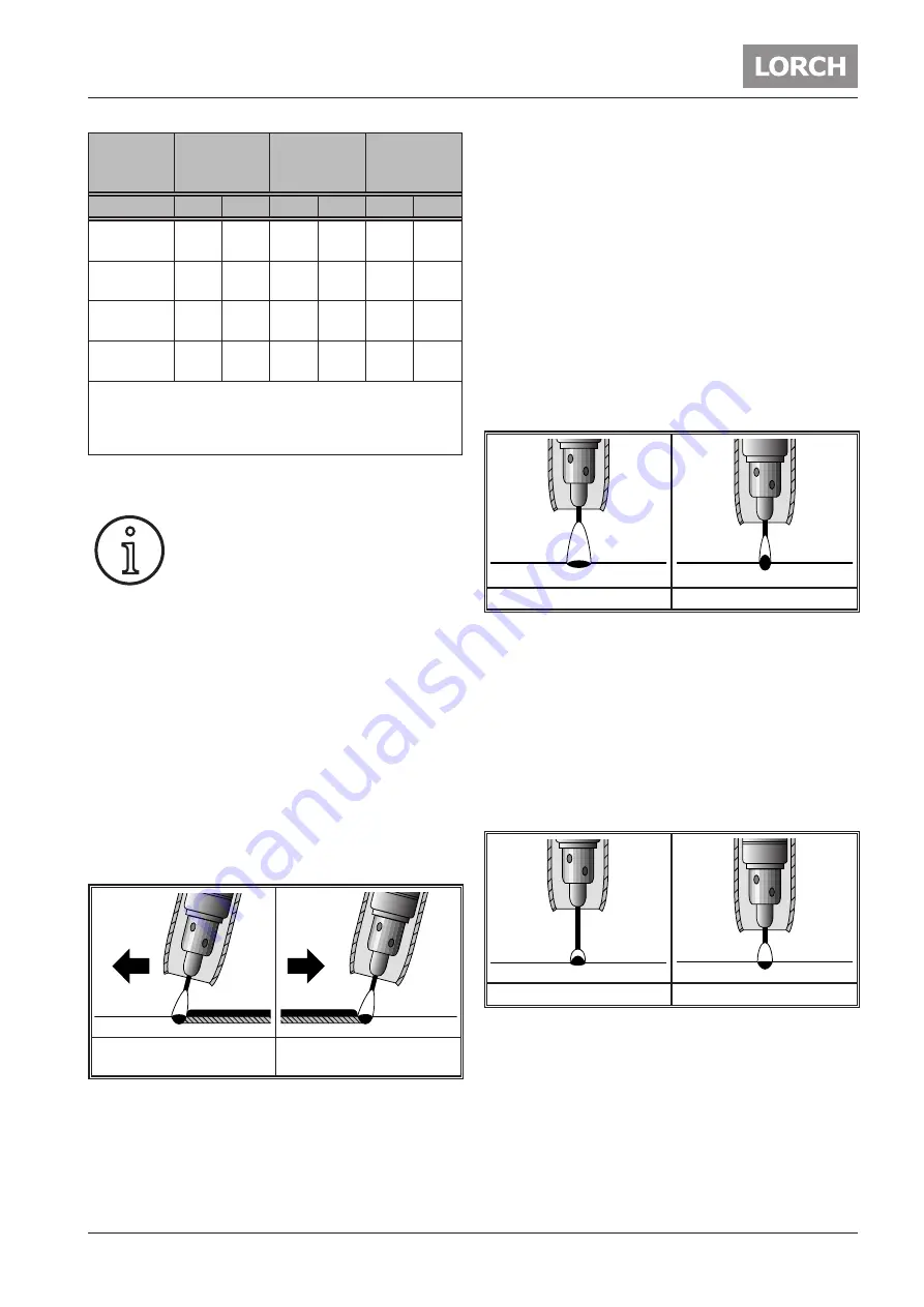
Wire elec-
trode di-
ameter
Long arc/
spray arc
Transition
arc
Short arc
mm
A
V
A
V
A
V
0,8
140…
180
23…
28
110…
150
18…
22
50…
130
14…
18
1,0
180…
250
24…
30
130…
200
18…
24
70…
160
16…
19
1,2
220…
320
25…
32
170…
250
19…
26
120…
200
17…
20
1,6
260…
320
26…
34
200…
300
22…
28
150…
200
18…
21
Good weld qualities are only achieved if the voltage and
current are well balanced.
When using CO2 an arc voltage which is around 3 V larger
than required when using argon-rich gas mixtures.
Tab. 8: Working ranges for MAG welding
Holding and guiding the torch
You can weld in all positions using metal
shielding gas welding: level, horizontal,
vertical down, vertical up, overhead and
diagonal.
For level and horizontal and level welds, hold the torch
vertically (neutral torch position) or pushing at up to 30°.
On thicker layers you can also drag the torch slightly.
The neutral torch position produces the best penetration
depth and inert gas coverage. Take care not to tilt the
torch too much, otherwise air could be drawn into the
inert gas shield by the injection effect.
If you are welding vertically and overhead then you should
push the torch slightly. Down welds are used mainly for
welding thin plates. In this case, hold the torch in as neu-
tral or slightly dragging position. This technique requires
specially trained and experienced welders, since there
are dangers from incomplete fusion due to the forward
melt pool. This danger increases with thicker materials,
or if the melt pool is very thin because the voltage is too
high.
Weld direction
pushing
Welding direction
dragging
Abb. 16: Torch position
Avoid larger oscillating movements in order to prevent
the melt pool from building up in front of the arc. This can
lead to incomplete fusion due to the forward melt pool.
Except in the vertical up position, you should oscillate
laterally only as far necessary to cover both edges of the
seam. If the seam is sufficiently wide, weld two beads
alongside each other.
If you are welding in the vertical up position, your oscilla-
tions should be in the shape of an open triangle.
Arc length correction
The longer the arc, the shallower is the penetration
depth, the wider and flatter the weld bead and the great
-
er the tendency to spatter. The weld metal is transferred
in slightly larger drops compared with a shorter arc. Use
a longer arc when fillet welding, in order to produce a flat
or concave weld bead.
A shorter arc increases the penetration depth (at the
same current intensity), the weld bead is narrower and
the tendency to spatter is reduced. The weld metal is
transferred in finer drops until the short arc is reached.
Long arc
Short arc
Abb. 17: Arc length correction
Electrode wire length
In general, the distance between the torch and the work-
piece is 10-12 times the wire diameter. You can also
change the torch distance to affect the length of the free
end of the electrode.
A longer free end of the electrode reduces the current
intensity and the penetration depth.
A shorter free end of the electrode increases the current
intensity while maintaining the same wire feed rate.
Long electrode end
Short electrode end
Abb. 18: Electrode wire length
i


