


REG. CODE
1-5302-509
MODEL N°
50778
DATE OF ISSUE
10.06.99
REVISION
00
DATE
10.06.99
ENDORSED
COMPILER TECO/ATI
60
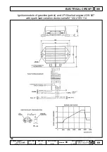
LGW 523 cut-off
In engine LGW 523, the module pilots an inductive load (coil of the
cut-off solenoid valve on the carburetor 2 fig. 147) by means of a
contact signal (on the idling speed adjuster screw) 1 fig. 147.
When the fuel throttle is released, the speed adjuster screw (which is
mounted on an insulating support) is grounded. A wire leads from
this screw to the module.
The module recognizes whether the throttle is being released when
the contact is grounded.
In this condition and if the engine rate is more than 2000 r/min, the
solenoid valve of the cut-off is closed to prevent fuel from flowing into
the idling duct.
This prevents fuel from being consumed when the engine is in the
release phase at high speeds.
The solenoid valve of the cut-off is powered by the module and this occurs when the engine operates (the module detects the
passage of the switching plate).
523 Ignition process
There is a support 1with two laminations set at 180° (fig. 146) on the timing pulley of the camshaft timing system.
The spark is supplied on each revolution on both cylinders (lost spark). The current runs from a high voltage contact of the
coil to the connected spark plug and from thence via the ground to the other spark plug subsequently returning to the coil via
the cable. The sparking instant is therefore necessarily the same for both spark plugs.
If one of the spark plugs fails to spark, the spark will also not strike on the other. If the spark plug discharges towards ground,
the other will not have a normal spark.
The two spark plugs operate with opposite polarities. The central electrode of one will be positive and the other negative (this
latter is more liable to wear).
Phase sensor
The phase sensor used to identify the correct phase angle, is a
sensor with Hall effect 1. It is activated by a magnet inside the sensor
itself.
The influence of the magnet is eliminated when lamination 5 is held
by sensor 1, thus determining an output signal.
The engine rotating speed is gauged by measuring the time that
elapses between two consecutive lamination passages.
The input instant of lamination 5 forms the reference for the
calculations made by the module to determine the firing point.
Three wires reach sensor 1: the black one is grounded, the red one is
connected to 15-54 of the ignition block (and, thus, to the b)
while the green one is connected to the module.
The green wire will not be powered if the sensor is free. A 5 Volt
value can be read if the sensor is held by the lamination.
Sensor 1 is positioned so that the voltage transmitted to the green
wire changes from 5 Volts to 0 with the crank shaft at 11° prior to
T.D.C.
Sensor 1 is glued to the cover of the camshaft. Its functionality can
be tested by connecting the relative test instrument which, when the
contact is made, checks whether the sensor is functional.
In the event of faults, the sensor cannot be repaired and must
therefore be replaced.
If the Hall effect sensor must be replaced, unscrew the three screws 2 fig. 148 to remove the lamination and take out the two
pins 3 fig. 148.
Immerse the pins in Loctite type 648BV when remounting.
After the timing pulley of the camshaft has been mounted complete with lamination 6, make sure that this sets into its
housing on the center-line of the sensor.
If the setting is less than perfect owing to accidental deformations in the lamination, its position must be restored as indicated
in 1-5
147
IGNITION
XII
148


