


COMPILER TECO/ATL
REG. CODE
1-5302-509
MODEL N°
50778
DATE OF ISSUE
10.06.99
REVISION
00
ENDORSED
DATE
10.06.99
51
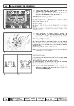
Carburetor
Engine LGW 627 is fuelled by two "DELLORTO" carburetors type
FHCD22-18.
Comply with the following instructions when adjusting:
- The air filter must have a clean cartridge.
- Air must not be drawn through vacuum pipes, seals, etc.
- Parts that use electric power must not be operating (electric fans,
alternator, etc).
If the carburetors are remounted, tighten the fixing nuts to an 8 Nm
torque and the stud bolts to a 5 Nm torque.
Speed adjuster screw regulation (idling rate)
Use a precision revolution counter.
Insert the exhaust gas analyzer probe into the exhaust pipe. Bring
the engine to operating temperature by allowing it to run at about
2000 r/min until the thermostat opens (do not allow the engine to
heat at idling rate alone as measurement of the "CO" content would
not be valid in these conditions).
Operate with the cold starting device deactivated.
Work on the speed adjuster screw 1 (see fig. 129) unable obtaining
a stable rate of 900 r/min.
Mixture adjuster screw regulation (idling rate)
Work on the idling mixture adjuster screw 1 (see fig. 129a) on both
carburetors in succession, first on one and then on the other, until
the "CO" content on the exhaust is 5 to 8 %.
If no exhaust gas analyzer is available, work on the above
mentioned screw until obtaining the highest r/min rate that this
adjustment allows.
Use the speed adjuster screw 1 (see fig. 129) again until obtaining a
rate of 1100 r/min.
Carburetor vacuum adjustment
Slacken off screws 1 (see fig. 130).
Mount the two stud bolts with calibrated holes and the relative
vacuum gauges in their place (see fig. 130a).
130
128
129a
129
FUELLING CIRCUIT
XI


