LOHBERGER VARIOLINE AC 105 Operating Manual Download Page 14

Page 14

Start-up fl ap

To facilitate initial heating, all LOHBERGER stoves are equipped with a start-up 
fl ap. Opening the start-up fl ap provides a direct route from the fi rebox chamber 
to the fl ue pipe. The fl ue gases then need not take the “long” route through 
the oven, but enter the fl ue pipe while still hot, rapidly establishing a fl ue drau-
ght. Once there is suffi cient draught in the fl ue and the initial heating phase is 
completed, close the start-up fl ap again. 
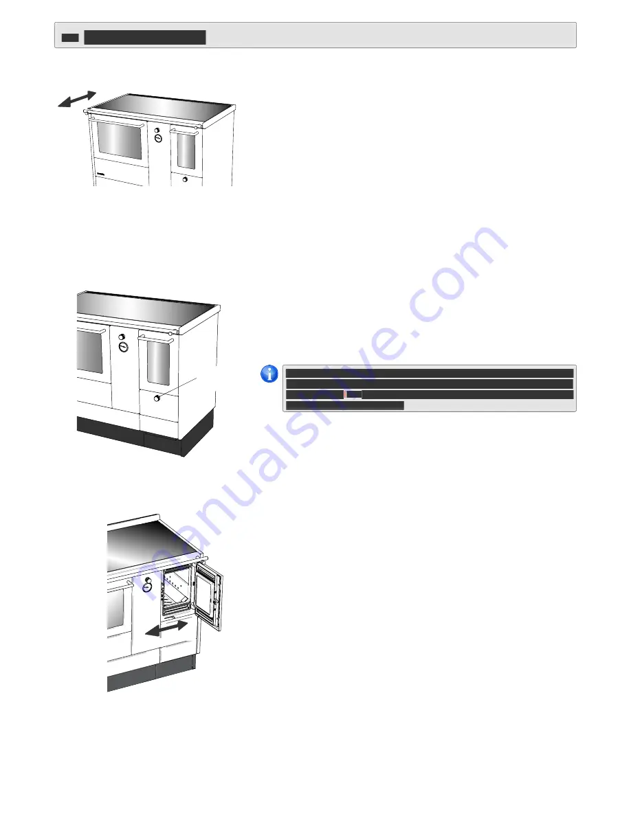
It is incorporated in the hand rail on the side opposite to the combustion cham-
ber. Pulled out is open; pushed in is closed (Figure 20). 
Caution:  The start-up fl ap must only remain open during the initial heating 
phase. If the start-up-fl ap remains open when heating, this will cause the stove 
to overheat and damage stove components. An open start-up fl ap will also 
result in increased fuel consumption.

Air control

The AquaTherm appliance is fi tted with an automatic output controller. This 
device serves to “restrict” the supply of combustion air; but this has only a 
limited effect on the output. It is defi nitely not suitable for compensating an 
excess of fuel. A certain amount of fuel requires a certain amount of oxygen for 
optimum combustion. If the wood is supplied with less air than is required for 
clean and effi cient combustion, less energy is generated in the appliance (pro-
tecting the appliance to a great extent from overheating) – the unused “wood 
gas”, however, escapes through the fl ue. 
The result: low effi ciency and high environmental load. 
Remedy: load the stove only up to the recommended fuel level. 

Primary air control

The supply of the primary air required for combustion is controlled with the 
rotary knob below the fi rebox door (Figure 21). This determines the rate of 
burning and therefore the heat output of the stove. 
In position “0” the controller is closed, no combustion air is supplied. In posi-
tion “1” minimum air supply is provided; select this position for slow-burning 
operation. Turning the rotary knob to position “6” means maximum air supply, 
necessary especially during the heating-up phase.


Air settings see Table on page 18

Secondary air control 

The supply of secondary air (combustion air fl owing over the fuel from the top) 
produces combustion that matches the fuel being used and keeps down the 
pollutant emissions. The secondary air fl ows through openings in the rear wall 
of the combustion chamber as well as from below and at the top along the 
combustion chamber door (along the viewing window, if present) over the fuel 
into the combustion chamber. 
The secondary air is controlled with the secondary air slider which is visible 
in the lower area after opening the fi rebox door (Figure 22). Moving the slider 
towards the outer wall of the appliance reduces the incoming secondary air 
fl ow; moving towards the oven increases it. 


Air settings see Table page 18

Figure 20

Figure 21

Figure 22

open 

closed

Max.

Min.

Control knob for 
primary air

Summary of Contents for VARIOLINE AC 105

Page 1: ...Issued 06 2016 OPERATING MANUAL with INSTALLATION INSTRUCTIONS GB VARIO LINE AQUA THERM COMBI AC 105...

Page 2: ...Outdoor air supply for combustion optional equipment 11 Examples of possible connections 11 9 Connection of the heating system 12 Heat output to water 12 Return flow temperature boost 12 Temperature...

Page 3: ...preparation DIN 4751 Part 2 Safety devices for heating systems with flow temperatures of up to 110 C 120 C in preparation open and closed water heating systems up to 349 kW 300000 kcal h with thermost...

Page 4: ...instructions regarding maintenance and cleaning in this operating manual Your chimney sweep will also be happy to clean the fireplace Only clean and properly adjusted appliances work efficiently 2 2...

Page 5: ...trolley Transport by means of carrying straps included in the delivery Remove the fuel drawer hotplate and transport securing devices hook the four carrying straps into the stove base Figure 4 Insert...

Page 6: ...12815 the Austrian standard NORM M 7550 the German industrial standards DIN 18882 DIN Plus BIMSCH as well as the special regulations concerning efficiency and pollutant emission applicable in Regensb...

Page 7: ...n Remove cooking plate s and slacken stove frame mounting screws 12 pi eces Figure 6 Correctly position stove frame retighten stove frame mounting screws 12 pieces Replace cooking plate s Base recess...

Page 8: ...nless steel 5 Sidewall 6 Control knob heating cooking operation 7 Thermometer 8 Fire door panel 9 Fire door handle stainless steel 10 Fire door viewing window extra charge 11 Control knob for primary...

Page 9: ...ing minimum distances from combustible building materials clearance to wall 20 cm clearance to ceiling 40 cm Figure 10 Figure 11 Figure 12 With fire protection unit retrofitted Gap in kitchen plinth t...

Page 10: ...pre fabricated components are preferable Assessment of the entire flue gas system according to DIN 4705 Parts 1 and 2 with shared flue systems according to Part 3 Connection stove chimney The flue pi...

Page 11: ...requirements for the operation Even with an outdoor air supply for combustion the requirements for the operation of an appliance independent of indoor air room sealed appliance are not fulfilled of an...

Page 12: ...ation and the calculation of the dimensions of the expansion tank must comply with DIN EN12828 and DIN EN13831 The expansion tank must be installed in rooms that are protected from frost For further d...

Page 13: ...of symbols 1 Installation package 1 Installation package 1 Installation package Integrated return flow temperature boost Integrated return flow temperature boost Integrated return flow temperature bo...

Page 14: ...his determines the rate of burning and therefore the heat output of the stove In position 0 the controller is closed no combustion air is supplied In posi tion 1 minimum air supply is provided select...

Page 15: ...be heat exchanger and the radiated losses to the room where the stove is installed via the cooking surface or the oven and consequently the heat output to the room are reduced COOKING OPERATION Figure...

Page 16: ...lames All three stages can occur at the same time from the inside to the outside of a piece of wood Clean combustion The first prerequisite for keeping pollutant emissions as low as possible is that o...

Page 17: ...ir to position 6 and fully open the slider for the secondary air Open the firebox door Turn the operation mode control to Cooking operation Put 2 small pieces of firewood onto the grate Place a piece...

Page 18: ...vered by warranty In any case this will lead to incomplete and inefficient combustion and subsequently to low efficiency with all appliances Cooking For cooking change the operating mode to cooking Co...

Page 19: ...iance components flue gas pipe cooking plate grate cleaning cover ash pan ensure they are correctly positioned and function as required and or that there are no leaks When positioning the cooking plat...

Page 20: ...ven If the appliance is overheated or if a gasket is damaged the inside of the glass viewing window of the oven may become fogged To clean it please proceed as follows Remove oven door as described an...

Page 21: ...velopment of unsightly spots on the cooking plate and the stove will keep its good appearance Take care that the expansion gaps of the steel cooking plate are always kept free of deposit build ups so...

Page 22: ...ave an abrasive effect on the shed around or have an abrasive effect on the shed around or have an abrasive effect on the glass ceramic surface This applies particularly to glass ceramic surface This...

Page 23: ...draught Have the stove plate aligned or replaced Seek the advice of your chimney sweep if necessary install a dam per Stove frame or stainless steel components discoloured Clean surfaces seek the advi...

Page 24: ...heat up Start up flap is open Close start up flap Incorrect chimney draught Contact your chimney sweep Output controller faulty Replace output controller Oven viewing glass becomes cloudy Stove overhe...

Page 25: ...0 3 cm Example Stove frame overhang front 0 cm flue pipe connection at the side 18 cm clearance installation wall to rear wall stove 6 cm 105 60 18 15 3 0 6 3 68 14 5 6 5 85 13 5 18 19 5 14 5 1 25 64...

Page 26: ...m position mm 100 250 Oven Width x height x depth mm 420 x 290 x 410 Cooking surface Width x depth mm 1008 x 507 Area m2 0 51 Ash drawer Stove litre 4 5 Fuel storage container Stove litre 34 5 Fuel co...

Page 27: ...ns REPAIRS We will carefully check your appliance and establish whether the warranty claim is justified If yes we will decide in which way the defect should be corrected In the event of a repair we wi...

Page 28: ...GMBH Landstra e 19 5231 Schalchen Austria Telephone 43 0 7742 5211 0 Telefax 43 0 7742 5211 109 of ce lohberger com www lohberger com Slight variations in colour due to printing process Subject to te...

Reviews: