GB
6
Pr
epar
ation
5..
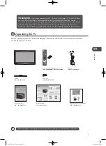
Mounting on the wall. This TV is designed to be wall-
mounted with a standard 200 mm x 100 mm mounting
kit designed for flat-panel TVs (sold separately).
Mount this TV according to the instructions included
in the mounting kit. Due to space restrictions, we
recommend that you make all connections (refer to
page 13-17 for details) before mounting on to the wall.
3..
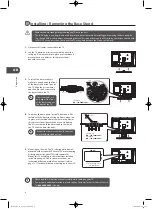
To install the base stand first
make sure you position the front
of the base stand at the front of
the TV. Align the 6 screw holes
and then use the 6 screws to fix
the base stand to the TV.
4..
To remove the base stand, lay the TV down on a flat
surface with the back side facing up. Please make sure
to place a soft cushioned material (such as a pillow or
thick piece of foam) beneath the screen. Untighten
the 4 screws that hold the base stand to the rear of
the TV. Slide the base stand out.
1..
Disconnect all cables connected to the TV.
2..
Lay the TV down on a flat surface with the back side
facing up. Please make sure to place a soft cushioned
material (such as a pillow or thick piece of foam)
beneath the screen.
screw
TV Front
Base Stand
Front
unscrew
.Installing./.Removing.the.Base.Stand
Screws x 3
(P.N.:.
xxxxxxxxxxx
)
Screw A x 6
(P.N.:.I.03.TP4016A01)
200.mm
100
.mm
Four mounting holes
(size M4 screw)
• Please read this instruction manual carefully while setting up your TV.
• If you require additional assistance please call our Customer Technical Services Centre.
Tel:
0844.800.6020
(UK only)
Keep all the spare screws should you want
to use the base stand option.
The screw holes will
only align if the front
of the base stand is at
the front of the TV.
• Remove the base stand before mounting the TV onto the wall.
• The LCD display is very fragile, and must be protected at all times when installing and removing the base stand. Be
sure that no hard or sharp object, or anything that could scratch or damage the LCD display, comes into contact with
it. DO NOT exert pressure on the front of the TV at any time because the screen could crack.
Screw A x 2
(P.N.:.I.03.TP4016A01)
Screw B x 2
(P.N.:.I.03.TP4012A01)
B
B
A
A
L26DVDB11_IB_110414_Annie.indd 6
11年4月14日 下午5:46
Summary of Contents for L26DVDB11
Page 2: ...L26DVDB11_IB_110414_Annie indd 2 11 4 14 5 46...
Page 69: ...L26DVDB11_IB_110414_Annie indd 69 11 4 14 5 47...
Page 70: ...L26DVDB11_IB_110414_Annie indd 70 11 4 14 5 47...
Page 71: ...L26DVDB11_IB_110414_Annie indd 71 11 4 14 5 47...
Page 72: ...L26DVDB11_IB_110414_Annie indd 72 11 4 14 5 47...


