background image

60

Troubleshooting

1N1 / 3N1

Any found fault or malfunction must be inspected and cor-
rected by a qualified person to guarantee the performance 
of the clearer system.

8.2  Analysis of rotors with 

unusual behavior

Rotors with unusual behavior, such as too many cuts, increased Q, F or P 
data etc., are an indication that something at this rotor position is different 
from the rest of the machine. This unusual behavior can have various causes, 
such as differences in the applied sliver, the spinning components or malfunc-
tions of the clearer.

In addition to the built-in diagnostic functions the LZE-V also provides informa-
tion for verifiying such clearers and for analyzing the source.

The easiest way to determine a rotor position with an unusual behavior is to 
use the Hitlist (

5.13.7 Hitlist

) since it displays most relevant production related 

values and data of the three sensors.
The mean or Std.Dev related values can indicate wrongly adjusted values, 
contaminations or malfunctions of the sensors or the spun material.
The surface related values can be an indication to wrong slivers or worn out 
spinning components.

If such a rotor position is identified the Events (

7.5.2 Events

) of the specific 

rotor can give an overview of the production behavior and history over the last 
few hours. Very short running times after piecing and the reason for the stop 
can be an indication of the source of the unusual behavior.

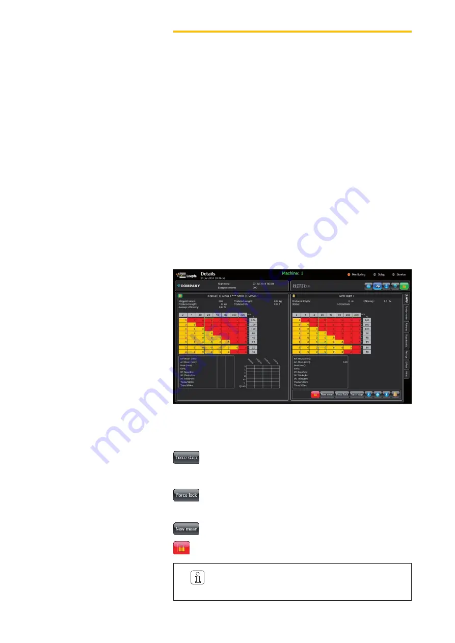
In case of doubts regarding the communication or the measured sensor val-
ues of a clearer, the following four buttons below the rotor data (

Monitoring > 

Details

) can be used for different actions.

Force stop:

 Checks the communication between LZE-V, SE-Board, 

sensing head and machine SE. The piecer starts the rotor again 
without operator intervention.

Force lock:

 Basically the same effect as Force Stop, but also blocks 

the spindle. Means the user has to unlock the rotor either with the 
unlock button or by making a new mean.

New mean:

 New adjustment to the yarn after the next piecing.

Unlock Rotor:

 Unlock the rotor position.

Summary of Contents for YARNMASTER 1N1

Page 1: ...YARNMASTER 1N1 3N1 46904003 en Version 2 X 08 2014 Instruction Manual LZE V ...

Page 2: ......

Page 3: ...al This Manual is protected by copyright and exclusively intended for internal purposes Complete or partial reproduction and dissemination of this Instruction Manual to third parties even in form of extracts as well as the use and or disclosure of the contents are not allowed without the written approval of Loepfe Brothers Ltd except for internal purposes YarnMaster is a registered trademark of Lo...

Page 4: ......

Page 5: ...l 11 1 3 2 Delivery 11 1 3 3 Technical Modifications 11 1 3 4 Improper or False Application 11 1 3 5 Inadequate Maintenance 11 1 3 6 Loss of Data 11 2 Safety 13 2 1 Responsibility of Operating Company 13 2 1 1 Basic Information 13 2 1 2 Responsibilities 13 2 2 Requirements for Personnel 13 2 2 1 Inadequate Qualification 13 2 2 2 Specialized Personnel 13 2 3 Use 14 2 3 1 Intended Use 14 2 3 2 Incor...

Page 6: ...al 29 5 2 2 Personnel 29 5 2 3 Intended Operation 29 5 3 Central Unit LZE V 30 5 3 1 Monitor 30 5 3 2 USB Interface 30 5 4 User Interface Navigation 31 5 4 1 Menu Overview 32 5 4 2 Function Buttons additional buttons explained per page 33 5 5 Language Selection 34 5 6 User Password 34 5 7 Data Entry 34 5 8 Base Settings 35 5 8 1 Configuration 35 5 8 2 Shifts 36 5 8 3 System 36 5 9 Group Administra...

Page 7: ... 51 6 2 Data Export Import 52 6 3 System Snapshot 54 6 4 Customer Logo 54 7 Inspection and Maintenance 55 7 1 General 55 7 2 Safety 55 7 2 1 Personnel 55 7 2 2 Electric Current 55 7 3 Spare Parts Accessories 55 7 4 Cleaning the Measuring Slot 56 7 5 Diagnostics 57 7 5 1 Versions 57 7 5 2 Events 57 7 5 3 Tests 58 7 6 Replacement of Sensing Head and SE Board 58 8 Troubleshooting 59 8 1 Hardware Lock...

Page 8: ... Foreign matter IPI Imperfections LZE V Loepfe central unit version V N S L T Neps shorts longs thin places OEM Original Equipment Manufacturer P Synthetic foreign matter Polypropylene Q Quality SE Section electronics SH Sensing head VCV Yarn irregularities ...

Page 9: ...rer performance trouble free operation as well as a high service life of the yarn clearer system 1 1 2 Duty to Read this Manual Prior to any work the personnel must have thoroughly read and understood this Instruction Manual and in particular the safety information 1 1 3 Availability of Instruction Manual The Instruction Manual is part of yarn clearer system YarnMaster 1N1 3N1 and must be kept in ...

Page 10: ...e components and assemblies Grounding connection Material damage DANGER WARNING CAUTION ATTENTION Indicates an imminently hazardous situation which will result in death or serious injury Indicates a potentially hazardous situation which may result in death or serious injury Indicates a potentially hazardous situation which may result in minor or moderate injury Indicates a potentially hazardous si...

Page 11: ...rom the following Unauthorized conversion and modification of the yarn clearer system The use of spare parts non OEM parts conversion parts not supplied by us 1 3 4 Improper or False Application Loepfe Brothers Ltd will not be liable for damage and accidents resulting from the following Improper user of the machine Failure to comply with the information and notices in this Instruction Manual 1 3 5...

Page 12: ......

Page 13: ...clearer system qualification training and employment of qualified personnel 2 1 2 Responsibilities The operating company shall define the responsibilities and competences for operation and maintenance of the yarn clearer system and appoint the responsible persons 2 2 Requirements for Personnel 2 2 1 Inadequate Qualification 2 2 2 Specialized Personnel The following qualifications for the different...

Page 14: ...e by unauthorized modifica tion of the yarn clearer system Z Z Conversions or modifications of the yarn clearer system must be agreed with Loepfe WARNING 2 3 Use 2 3 1 Intended Use Yarn clearer system YarnMaster 1N1 3N1 has been designed and built for online yarn monitoring and clearing of undesired yarn faults on openend spin ning machines from various manufacturers The yarn clearer system must b...

Page 15: ...T touch soldered connectors pin contacts printed circuits or electronic components ATTENTION For detailed information on the safety devices e g emergency stop button See Instruction Manual of the openend spinning machine 2 4 3 Electrostatic Charging 2 5 Safety Devices Emergency stop Button Yarn clearer system YarnMaster 1N1 3N1 is integrated in a openend spinning machine and has no additional safe...

Page 16: ......

Page 17: ...ines from various manufacturers The collection of the yarn faults is based on the optical measuring principle 3 2 Equipment Configuration Yarn clearer system YarnMaster 1N1 3N1 consists of the following components Central unit LZE V Section electronics SE Sensing head TK YM 1N1 3N1 External power supply 24 VDC 90 264 VAC Central unit LZE V Optional Power supply unit 24 VDC Section Electronic SE 20...

Page 18: ... transfer Central unit software Functions Control and monitoring of yarn clearing Communication with sensing heads transfer of clearer settings Processing logging and saving of operating and quality data LZE V Connections Front USB interface USB port for import export of settings and data as well as screenshots A removable cap protects the USB interface from dust and humidity ...

Page 19: ...D green red Power supply OK HDD LED red Compact flash drive active Microswitch Power ON OFF LED green Tap 1 second Switch to standby mode controlled by operating system LED becomes orange LED green Press 1 second Only in emergencies Forced uncontrolled switch to standby mode LED becomes orange Unsaved data are lost LED orange Tap 1 second Start LED becomes green LAN 1 LAN 2 RJ45 Port LAN 10 100 10...

Page 20: ...ections of yarn faults TK YM 3N1 Collections of yarn faults foreign matter and synthetic foreign matter PP PE etc Sensing Head Variants Yarn Count Range TK YM 1N1 3N1 Limit range coarse Nm 5 0 Nec 2 95 Limit range fine Nm 100 Nec 59 05 The SE board is the interface between the control unit and a section of sensing heads It processes all quality data from the sensing heads 3 2 2 Section Electronic ...

Page 21: ...bit Green on Red off Q lock Red Ref mean lock Ref Mean Green slow blink Red off Q lock Red Thin thick yarn count lock Ref Mean Green fast blink Red off Q lock Red Thin thick sliver lock Sliver Green off Red on Q lock Red Quality lock Pearl lock Quality F lock Purple F cluster lock long F_130 F_LCK F Green off Red fast blink Q lock Red Moiré lock Moiré Green on Red slow blink F lock Purple F lock F...

Page 22: ...fication Foreign matter cluster clearing Quality Clearing N Neps S Short Faults L Long faults T Thin places Yarn count channel Thin and thick count Sliver channel Thin and thick sliver Moiré Piecer clearing depends on machine type Yarn irregularities CV Imperfections IPI Classification of faults Online laboratory Graphics Q Pack Variation of yarn CVy Variation of hairiness CVh Variation of sliver ...

Page 23: ...n Central unit Sensing head Article description Article number Order number 3 5 1 Type Plates Serial number Calendar week year ZE YM 1N1 LZE V XXX 46872000 FFFFFFSSSSKWJJ 46760000 1004153 4213 0001 Loepfe article number Order number Barcode Consecutive serial number Calendar week year Loepfe article number Barcode YM 1N1 YM 3N1 905264000 Full 1000174 0412 Calendar week year Order number ...

Page 24: ......

Page 25: ...E V LZE V Color display with graphics capability backlit touch screen 15 6 inches Connection All types of machine 24V DC SELV 25 15 Max current 4A Fuse 2xT3 15AL Capacity of OE Spinning machine Max 700 rotors Settings side Up to 2 settings depending on machine type Dimension Approx 483 x 266 x 70mm W x H x D Max power consumption Typically 30 Watt Weight Approx 5 0kg Printing Printout via USB stic...

Page 26: ...ter deviation 38 20 to 99 0 Sliver stops Thin place Length 3m Diameter deviation 18 1 to 9m 2 to 30 0m Thick place Length 3m Diameter deviation 18 1 to 9m 2 to 30 0m Yarn count lock Disabled Length 10 to 1000m Deviation 0 3 to 20 0m Neps or pearl channel Neps with respect to the reference mean 50 5 to 170 0 Spectrogram analysis Maximum statistically secured wavelength 300m 37 to 300m 0m Spectrogra...

Page 27: ...to 9 1 highest sensitivity 0 Locks Long cluster detection 2 1 to 9 1 highest sensitivity 0 Lock 5 stops per 5000m 1 to 9 stops per 1000 to 16000m 0m 10 4 Default values Valid values To disable set to Matrix lengths in mm 16 22 28 34 40 160 198 2 to 20 18 to 26 24 to 32 30 to 38 36 to 44 42 to 50 48 to 200 and between the lower length 2mm and the higher length 2mm Matrix intensity values 5 10 15 20...

Page 28: ......

Page 29: ...led for all openend spinning machine types via central unit LZE V Machine specific differences in operation or in the settings are possible and have been stated accordingly in the instructions All clearer functions are described in this Instruction Manual Individual functions are not available depending on the clearer components installed and the software options Prior to any work the personnel mu...

Page 30: ...se a pointed metallic object as this could damage the monitor surface X Do NOT clean monitor with aggressive cleaners 5 3 Central Unit LZE V 1 User interface 2 USB interface 5 3 1 Monitor Operation entry is performed by applying light pressure on the touch sensi tive screen touch screen of the monitor 5 3 2 USB Interface USB interface for import export of settings and data and for screenshots A re...

Page 31: ...level menu navigation 3 1st level tab navigation 4 2nd level tab navigation 5 Detail page 6 Lock unlock 7 Language selection 8 Help 9 USB device 10 Page name 11 Date and time 12 Shift start date and time Number of stopped rotors 13 Machine number 14 Machine type 10 11 13 14 12 5 1 2 6 7 8 9 4 3 ...

Page 32: ...oreign matter Polyprop Stops and Locks Piecings Q Pack Hitlist Quality Foreign matter Polyprop Reports Setup Machine Configuration Shifts System Articles Quality Foreign matter Polyprop Production groups Service Diagnostics Versions Events Tests Loggings External Input Output Force stops ...

Page 33: ...ling Switch machine side Refresh the displayed data Warm restart Cold restart reboot the SCU Switch hitlist order Scroll the list Replace the settings by the default settings Touch Yes to apply the default settings Undo changes Add remove rotors Save the entered data all changes need to be confirmed Touchscreen calibration Show events for all rotors Filter events Rename article Archive manipulatio...

Page 34: ...letters and alternative characters with Cap and or Alt Gr button 5 7 Data Entry A data input window opens for all setup changes Information about the selected parameter the possible limit range for the parameter and the incrementation value is shown on the top of the data entry window Data entry needs to be confirmed twice with once in the data entry window and once in the corresponding main windo...

Page 35: ...et efficiency Once the efficiency of the selected production group or the entire machine is below the set value the efficiency on the Overview screen will be displayed in red Enable external language only possible with a 4k or CAN connection that provides this data Select your measuring system Select your GUI theme Light trees Optional if a light tree is connected to the LZE V Set an individual pa...

Page 36: ...ible to set up to 7 different shift cycles manually Therefore determine the shift cycle per day 2nd column Shift reports Set the time to keep reports in the memory Set the report language Set the report measuring system Setup Machine System Date Time Set date time and time zone of the LZE V Network Set a network connection for remote access 5 8 2 Shifts 5 8 3 System ...

Page 37: ...e The rotor range of a group can be selected by enlarging or reducing the size of the transparent window on the rotor overview 1 Tap the production group of which you wish to set the range 2 Select a color in which the group should be displayed in the overview 3 Select the rotors for the production group by enlarging or reducing the transparent window 1 4 Press to add selected rotors to a group pr...

Page 38: ...tick the box of the production group that you want to change and confirm A lot change as well as a shift change will be forced Initiate a lot change After changing the yarn count After changing the lot After changing the spinning parameters on the machine After changing the of the take up speed After an interruption of more than 24 hours Fixed speed You can enter a fixed take up speed if necessary...

Page 39: ...e different yarn clearer functions by ticking the box next to the specific clearer channels 5 10 1 Archive Administration The LZE V can work with 10 active articles These articles can be selected and modified directly as shown before It is also possible to save a higher number of different article settings These articles are saved in the article archive Press the archive button to open the archive...

Page 40: ...shown in the data entry window while changing a setting 5 11 1 Quality Q 1N1 3N1 The yarn clearing to control the yarn structure is activated by setting classes within the clearer matrix The length and deviation limits of the classes can be set individually within certain limits 1 Enter the yarn count to the intended window The right yarn count is nec essary for the calculation of the production w...

Page 41: ...e referenced machine side 5 11 2 Foreign Matter F only 3N1 Foreign matter clearing is activated by setting classes within the clearer matrix The length and deviation limits of the classes can be set individually within certain limits Sensitivity SC SdC sensitivity for short cluster possible to remove during piecing Sensitivity LC sensitivity for long cluster locks cannot be removed during piecing ...

Page 42: ...dC sensitivity for short cluster possible to remove during piecing Sensitivity LC sensitivity for long cluster locks cannot be removed during piecing They must be removed manually Lock condition repeated P stops within the set length In case of a lock check the sliver for contaminants and remove the yarn from the package The sensitivity can be set from 1 to 9 Setting 1 is the most sensitive Choose...

Page 43: ...ls Monitoring Details of the selected rotor Efficiency Shows the actual efficiency of the selected production group as well as of the entire machine As per the set target efficiency the numbers will get displayed either in red below target or in green above target The target efficiency can be set in Setup Machine Configuration In addition to the actual efficiency the efficiency trend of the last t...

Page 44: ...stops Produced length since shift start Average eff of the machine since shift start Produced weight of the production group since shift start Produced Rh Rotor hours of the machine since shift start Specific information of the rotor Produced length since shift start Efficiency of the rotor since shift start Status current state of the rotor Monitoring Details 5 13 1 Quality Chart for all Clearer ...

Page 45: ...ific information of the rotor Produced length since shift start Status current state of the rotor 5 13 2 Foreign Matter Displays polypropelene cleaning data for the production group as well as a particular rotor of the same group Specific information of the production group Stopped rotor total stops Produced length since shift start Specific information of the rotor Produced length since shift sta...

Page 46: ... shift start Quality generally amount of the particular state since shift start HW Dust Lock amount of the particular state since shift start depends on machine type Reports the classification of all faulty attempts during the piecing phase of the production group as well as a particular rotor Information on the last piecing is also provided 5 13 4 Stops Locks 5 13 5 Piecings ...

Page 47: ... maximum value Spectrogram Helps to analyze the yarn diameter profile for the presence of periodically occurring deviations Sample required length for a picture of the spectrogram Mean reference mean CVh CV hairiness CV on 2 mm CVy CV yarn CV on 8 mm CVs CV sliver CV on 500 mm Y axis relative to the max amplitude CVL Curve Analysis of the CV of a certain length 5 13 6 Q Pack ...

Page 48: ...ulating chain SdC Seeds Cluster short cluster accumulating distributed LC Longs Cluster long cluster accumulating Also displays those counted even if cluster settings are not active Polypropylene Displays the rotors with the highest or lowest measured or calculated P values A variance of the signal for the displayed rotors D classified defects S short defects SC Shorts Cluster short cluster accumu...

Page 49: ...d clearer setting At the same time data collection for the new report is started The completed report will be saved as pdf file on the LZE V The LZE V can save reports up to 60 days The default setting is 7 days but this setting can be changed in Setup Machine Shifts see chapter 5 8 2 Shifts After the set time frame is reached the older report is automatically deleted It is also possible to copy t...

Page 50: ......

Page 51: ...an authorized LOEPFE service technician only 6 USB Export Import The LZE V contains a USB port on the front panel of the central unit When a USB stick is inserted into the USB port the USB device icon is displayed in the header When the USB device icon is tapped a window opens displaying the possible actions 6 1 Upgrades The LZE V recognizes when a GUI software update file is available on the inse...

Page 52: ...ts to USB device Once one of the possibilities USB Actions is chosen and confirmed a win dow opens showing the directory of the USB stick In this window the folder to save the wanted data can be selected When exporting the reports the popup window includes a calendar in addi tion to the directory The calendar can be used to only export reports between two specific dates By pressing the button all ...

Page 53: ... an active article 1 of the 10 1 First select the location of one or more article files xml format 2 Then click the article file that has to be uploaded 3 Select the location where you want the article to be uploaded archive or one of the not grayed out active styles non active articles 4 Click the button to add the article to the location of your choice nothing has happened yet 5 Use the button t...

Page 54: ... as a folder named snap shot_YYMMDD_hhmm For further analysis the whole folder should be compressed and sent to the official Loepfe service representative 6 4 Customer Logo The LZE V offers the possibility to create and upload a customized logo to the GUI The logo is shown in the machine header of every menu screen Load customer logo Once the action is chosen and confirmed a window showing the dir...

Page 55: ...ne voltage frequency and with grounded protective ground conductor DANGER Safety risk with non original spare parts or non approved accessories Non original spare parts or non approved accessories could affect safety and cause damage malfunctions or total fail ure of the yarn clearer system Z Z Only use original spare parts or accessories approved by Loepfe ATTENTION 7 Inspection and Maintenance 7...

Page 56: ...r dust lock both sensor LEDs on 7 4 2 With Only use the cleaning swabs from LOEPFE part no 16964900 Use it either dry or dampened with optical lens cleaner 7 4 3 How Drag the soft tip of the cleaning stick a few times through the measuring slot When the LEDs go out automatically after removing the cleaning stick the sensor is cleaned correctly Do not use any hard sharp objects Do not immerse the s...

Page 57: ...tually installed on the SE boards and the sensing head The information on the installed software versions is important for any support communication 7 5 2 Events The events list shows a summary of all stops of either the machine or a par ticular rotor It is especially useful to assess the behavior of individual rotors on the rotor level The event data contains the following columns Rotor Date Time...

Page 58: ...as well as the communication of the interface connections between the SE and the machine section electronics When starting the test each rotor of the chosen rotor range will go into a forced lock one by one starting with the smallest rotor number At the same time the rotor position will also switch to red if the interface cable between the SE and the machine section electronic is connected the rig...

Page 59: ... low Yarn position wrong SH lower ceramic missing SH defective Check Yarn position and guiding Replace SH Hardware SE lock 3 Measured Yarn signal is too high Measuring slot obstructed by dust or lint SH defective Remove dust or lint Replace SH Hardware SE lock 4 Too many Run Stop transitions in the measured yarn signal Maximum piecing attempts reached default 20 per shift Yarn position wrong SH de...

Page 60: ...can indicate wrongly adjusted values contaminations or malfunctions of the sensors or the spun material The surface related values can be an indication to wrong slivers or worn out spinning components If such a rotor position is identified the Events 7 5 2 Events of the specific rotor can give an overview of the production behavior and history over the last few hours Very short running times after...

Page 61: ... standard deviation Std Dev Standard deviation value from adjustment at the lot start or from a forced mean by the user A Variance of the actual value Ar Variance running As Variance stopped D 100m Classified defects matrix S 100m Short up to 80mm SC Shorts Cluster Short cluster accumulating chain SdC Seeds Cluster Short cluster accumulating distributed LC Longs Cluster Long cluster accumulating L...

Page 62: ...Loepfe Brothers Ltd 8623 Wetzikon Switzerland Phone 41 43 488 11 11 Fax 41 43 488 11 00 info loepfe com www loepfe com Subject to technical modifications ...

Reviews: