Lochinvar LBT Series Installation, Commissioning, Maintenance And User Instructions Download Page 8


a)


Be at least one pipe size larger than the nominal outlet size of the safety device unless its total equivalent hydraulic 
resistance exceeds that of a straight pipe 9m long i.e. discharge pipes between 9m and 18m equivalent resistance 
length should be at least two sizes larger than the nominal outlet size of the safety device, between 18 and 27m at 
least 3 sizes larger, and so on. Bends must be taken into account in calculating the flow resistance. 

An alternative approach for sizing discharge pipes would be to follow BS6700 Specification for design installation, testing 
and maintenance of services supplying water for domestic use within buildings and their curtilages. 

b)


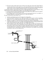
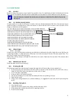
Have a vertical section of pipe at least 300mm long, below the tundish before any elbows or bends in the pipework. 

c)


Be installed with a continuous fall of at least 1 in 200. 

d)


Have  discharges visible  at  both  the  tundish  and  the final  point  of  discharge  but  where this is  not  possible  or is 
practically difficult there should be clear visibility at one or other of these locations. 

Examples of acceptable discharge arrangements are: 
 

I.


Ideally below the fixed grating and above the water seal in a trapped gulley. 

II.


Downward discharges at a low level; i.e. up to 100mm above external surfaces such as car parks, hard standings, 
grassed  areas  etc.  are  acceptable  providing  that  where  children  play  or  otherwise  come  into  contact  with 
discharges, a wire cage or similar guard is positioned to prevent contact whilst maintaining visibility. 

III.


Discharges at a high level; e.g. into a metal hopper and metal down pipe with the end of the discharge pipe clearly 
visible (tundish visible or not) or onto a roof capable of withstanding high temperature discharges of water and 3m 
from any plastic guttering systems that would collect such discharges (tundish visible). 

IV.


Where a single pipe serves a number of discharges, such as in blocks of flats, the number served should be limited 
to not more than 6 systems so that any installation can be traced reasonably easily. The single common discharge 
pipe should be at least one pipe size larger than the largest individual discharge pipe to be connected. If unvented 
hot water storage systems are installed where discharges from safety devices may not be apparent i.e. in dwellings 
occupied by blind, infirm or disabled people, consideration should be given to the installation of an electronically 
operated device to warn when discharge takes place. 
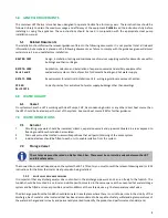


7.2.2


RELIEF VALVE DISCHARGE PIPEWORK


TUNDISH

METAL DISCHARGE PIPE (D1) FROM
TEMPERATURE RELIEF VALVE
TO TUNDISH

SAFETY DEVICE
(e.g. TEMPERATURE
RELIEF VALVE)

DISCHARGE PIPE (D2) FROM
TUNDISH, WITH CONTINUOUS FALL

FIXED GRATING

TRAPPED GULLY

DISCHARGE IDEALLY BELOW
FIXED GRATING

300mm MINIMUM

600mm MAXIMUM

Summary of Contents for LBT Series

Page 1: ...BT5000 LBT1000 LBT6000 LBT1500 LBT8000 LBT2000 LBT10000 LBT2500 LBT THERMAL STORE Installation Commissioning Maintenance and User Instructions READ AND UNDERSTAND THE INSTRUCTIONS Read and fully understand all instructions before attempting to operate maintain or install the unit ...

Page 2: ...1 BLANK PAGE ...

Page 3: ...2 Storage Vessel 6 7 2 1 relief valve discharge pipework 6 7 2 2 relief valve discharge pipework 7 8 0 COMMISSIONING AND TESTING 8 8 1 Electrical Installation 8 8 2 Water Connection 8 8 3 Primary Heat Source 8 8 4 Commissioning Check List 8 9 0 WARRANTY 9 10 0 DECLARATION OF PERFORMANCE 10 11 0 MAINTENANCE 11 11 1 General 11 11 2 1 1 Maintenance Schedule 11 11 3 Other Checks 11 11 3 1 relief valve...

Page 4: ...nstaller engineer according to all applicable standards and regulations 2 1 General description of safety symbols used BANNED A black symbol inside a red circle with a red diagonal indicates an action that should not be performed WARNING A black symbol added to a yellow triangle with black edges indicates danger ACTION REQUIRED A white symbol inserted in a blue circle indicates an action that must...

Page 5: ... 548 n a Insulation Thickness mm 100 100 100 100 100 100 100 Insulation Material Ecozero Ecozero Ecozero Fire Class HBF HBF HBF HBF b1 b1 b1 Description Unit LBT3000 LBT4000 LBT5000 LBT6000 LBT8000 LBT10000 Storage Capacity litres 3000 4000 5000 6000 8000 10000 Empty Weight kg 346 492 582 684 823 973 Floor Load weight unit storage capacity kg 3346 4492 5582 6684 8823 10973 Maximum Working Pressure...

Page 6: ...5 H Total Height with insulation mm 2720 2810 2870 2790 3490 4240 H Height of AAV Connection mm 2720 2810 2870 2790 3490 4240 De Diameter of Water Heater with insulation mm 1450 1600 1800 2000 2000 2000 Size Description Unit LBT300 LBT500 LBT800 LBT1000 LBT1500 LBT2000 LBT2500 sa Connection Air vent BSP 1 1 1 1 1 1 1 g Connection Tank body BSP 1 1 1 1 1 1 1 mc Connection ASHP flow BSP 1 1 1 1 1 1 ...

Page 7: ... heat source then the LBT should be treated as per the rest of the system See main heat source ICM for further guidance 7 0 WATER CONNECTIONS 7 1 General 1 Circulating pipework should be insulated cisterns expansion vessels and pipework situated in areas exposed to freezing conditions should also be insulated 2 Drain valves must be located in accessible positions that will permit draining of the e...

Page 8: ...r parks hard standings grassed areas etc are acceptable providing that where children play or otherwise come into contact with discharges a wire cage or similar guard is positioned to prevent contact whilst maintaining visibility III Discharges at a high level e g into a metal hopper and metal down pipe with the end of the discharge pipe clearly visible tundish visible or not or onto a roof capabl...

Page 9: ...oughly flushed out with cold water without any circulating pumps in position Ensure all the valves are open 8 3 Primary Heat Source The primary heat source operating in conjunction with the LBT Thermal store should be installed and commissioned in accordance with the relevant ICM Instructions provided 8 4 Commissioning Check List Failure to follow and complete the commissioning procedure and check...

Page 10: ...ioning and Maintenance Instructions and does not cover failures due to deliberate misuse malicious damage neglect unauthorised alterations or repairs accidental damage or third party damage b The LBT Thermal store remains installed at the original site of installation c Working temperature must be no greater than 95 C and MWP pressures must not exceed the figures given in the table above Exclusion...

Page 11: ...ve been manufactured inspected and pressure tested in accordance with the requirement of the European Pressure Equipment Directive PED 97 23 EC Article 3 Paragraph 3 of DL 25 Feb 2000 n 93 Conditions of use 1 The installation instructions have been followed 2 Fluids being passed through the heat exchanger are non hazardous in the group 2 category 3 The maximum working pressures and temperatures as...

Page 12: ...2 11 5 Draining the LBT The following procedure must be observed to prevent damage to the LBT and ancillary items connected to it 1 Ensure any heat source connected to the LBT is either turned off or disconnected from the LBT if safe to do so check the ICM of the heat source before any further action is taken 2 Turn off the water if applicable 3 Connect a hose to the system drain valve 4 Locate ho...

Page 13: ...installer If very hot water exits from either valve switch off the heat source immediately and isolate the electricity supply to the cylinder and separate heat source 13 0 ERP DATA TABLE Information Symbol Unit Value Trade mark Lochinvar Limited Model Identifier LBT300 LBT500 LBT800 LBT1000 LBT1500 LBT2000 Energy efficiency class B C C C C C Standing loss W 67 7 114 1 132 7 125 4 146 5 189 5 Stora...

Page 14: ...MP GAS CONDENSING BOILERS OTHER PLEASE SPECIFY WHAT IS THE MAXIMUM FLOW RETURN TEMPERATURE OF THE PRIMARY HEAT SOURCE s FLOW RETURN WHAT IS THE MAXIMUM WORKING PRESSURE OF THE PRIMARY HEAT SOURCE s HAS A T P VALVE BEEN FITTED TO THE BODY OF THE LBT IF YES IS THE LBT CONNECTED TO AN AUTOMATIC TOP UP EITHER DIRECTLY OR VIA THE HEATING CIRCUIT ...

Page 15: ...14 NOTES ...

Page 16: ...15 ...

Reviews: