6
5.0
GENERAL REQUIREMENTS
The Lochinvar LBT thermal store has been designed to operate trouble free for many years. These instructions should be
followed closely to obtain the maximum usage and efficiency of the equipment. PLEASE read the instructions fully before
installing or using the appliance. These instructions should be read in conjunction with the appropriate Heat pump
installation manual.
5.1
Related Documents
The installation should follow the relevant guidance offered in the following documents. It is not practical to list all relevant
information, but emphasis is placed on the following documents, as failure to comply with the guidance given will almost
certainly result in an unsatisfactory installation:
BS 6700: 1997
Design, installation, testing and maintenance of services supplying water for domestic use within
buildings and their curtilages
BS 7074: 1989
Application, selection and installation of expansion vessels and ancillary equipment for
Parts 1 and 2
sealed water systems. Code of practice for domestic heating and hot water supply
BS 7671: 2008
Requirements for electrical installations, I.E.E. wiring regulations seventeenth edition
CP 342:
Code of practice for centralised hot water supply-buildings other than dwellings
Part 2 1974
6.0
WATER QUALITY
6.1
Vessel
On systems where the LBT is working with Heat Pumps, CHP, Gas condensing boilers or any other direct heat source then
the LBT should be treated as per the rest of the system. See main heat source ICM for further guidance.
7.0
WATER CONNECTIONS
7.1
General
1.
Circulating pipework should be insulated; cisterns, expansion vessels and pipework situated in areas exposed to
freezing conditions should also be insulated.
2.
Drain valves must be located in accessible positions that will permit draining of the entire system.
3.
Individual valves should be fitted to each unit to enable isolation from the system.
7.2
Storage Vessel
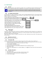
The safety valve must be rated no higher than 5 bar. There must be no isolating valves between the LBT
and this safety valve.
The connections used will depend upon the system the LBT is fitted to; you must consult the relevant drawing and /or ICM
instructions for the Solar thermal or Heat pump also being installed.
7.2.1
RELIEF VALVE DISCHARGE PIPEWORK
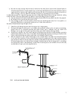
It is important that any discharge water does not collect in the discharge pipe-work and can run freely to the tundish. The
tundish should be mounted in a vertical and visible position located in the same space as the unvented hot water storage
system and be fitted as close as possible and within 600mm of the safety device e.g. the temperature relief valve.
The discharge pipe from the tundish should terminate in a safe place where there is no risk to persons in the vicinity of the
discharge, be of metal or other material that has been demonstrated to be capable of safely withstanding temperatures of
the water discharged and is clearly and permanently marked to identify the product and performance standard, and:


