background image


Page 14 


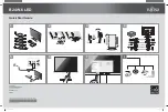
Video Wall Controller Cable Connection


1.


12V DC input power for MDU 

2.


DVI-I source/cable input from TVone scaler (#6) 

3.


6 x CAT7 D-SUB type 9P cable to Litile34 modules 

4.


12V DC input power for TVone scaler 

5.


DVI-D input source from media player or PC 

6.


DVI-I output source to MDU   


Summary of Contents for Litile34

Page 1: ...4 OPERATION MANUAL Seamless Tiled Panel Wall Solution for Large Area Digital Signage Display 1st Edition 3 25 2009 All information is subject to change without notice Approved by Checked by Prepared by Ming Hank Jack ...

Page 2: ...Page 2 RECORD OF REVISION Version and Date Page Old Description New Description Remark Mar 25 2009 all Preliminary Release ...

Page 3: ...he Litile34 modular display 8 2 0 Litile34 System Diagram 9 3 0 Connecting Power To The Litile34 Display 10 4 0 Setting up the Video Wall Controller 13 5 0 Displaying an image 15 6 0 Settings for Scaler and MDU controller 16 7 0 Troubleshooting 20 8 0 Maintenance and Services 21 ...

Page 4: ...of Litile34 s products we support its policy and ask you to be aware of how to dispose of this product The crossed out wheelie bin symbol illustrated above and found on our products signifies that this product should not be disposed of in general waste or landfill Please contact your local dealer national distributor or Technical Services for information on product disposal Restriction of the use ...

Page 5: ...hould be worn when lifting or handling the units Appropriate lifting equipment should be used Modules should not be lifted by one person The equipment must be installed securely and bolted to the ground to avoid toppling Each module must be bolted to each of its neighbouring modules and if necessary securely attached to a fixing point above the display to avoid toppling A structural engineer shoul...

Page 6: ...ler z 4 1 x CAT7 D SUB 9P signal cable 6000 mm z 5 1 x DVI D Cable 3000 mm z 6 1 x TVone C2 2000 Series Video Scaler Package including 1 x C2 2200 Video Scaler 1 x Power Adapter 12V 3 3A output for video scaler 1 x Power Cord 1830 mm 1 x C2 2000 Series Video Processor Operation Manual If any of these items should be missing or damaged please contact your distributor or sales representative immedia...

Page 7: ...l Wall Display Litile34 Video Wall Controller MDU TVone C2 2200 Video Scaler Package Optional Accessories xxxxxxxxxxxx CAT7 D SUB 9P signal cable 6000 mm 840612051101 Adapter 12V 5A 60W for MDU Controller 810618301010 Power Cable USA Type 810618301090 Power Cable Europe Type 810618301030 Power Cable Japan Type ...

Page 8: ...itioning for cooling This equipment is designed for safe operation at ambient temperatures between 5 C and 25 C For optimum performance the ambient temperature should be maintained between 10 C and 20 C The rear should not be obstructed The modules should be a minimum of 1m from any wall Rear access is required for servicing purposes Refer to the Installation Instructions for details of how to mov...

Page 9: ...Page 9 2 0 Litile34 System Diagram Your Litile34 Sunlight Viewable Seamless Tiled Panel Wall Solution s system diagram shown as below Litile34 System Block Diagram ...

Page 10: ...on BEFORE the modules to ensure the correct boot up sequence for the modules The Modules are powered by 220 to 240V 50 60 Hz AC single phase mains An earth connection is essential through the mains plug supplied For installations requiring more power than available from a single ring main a three phase supply should be prepared Please contact Litemax for further detail if this is required In line ...

Page 11: ...Page 11 Daisy Chain in line delay smart board Normal setting 5 seconds delay setting 10 seconds delay setting 15 seconds delay setting ...

Page 12: ...Page 12 20 seconds delay setting ...

Page 13: ...rive up to six Litile34 modules in a number of different configurations The modules are connected to the MDU controllers via a CAT7 cable with 9 pin D type connectors as supplied Four Video Wall Controllers TVone Scaler and MDU Controller sets Each set will drive up to 6 Litile34 modules Video Wall Controller Control and Features Front View Video Wall Controller Connectors Back View ...

Page 14: ...tion 1 12V DC input power for MDU 2 DVI I source cable input from TVone scaler 6 3 6 x CAT7 D SUB type 9P cable to Litile34 modules 4 12V DC input power for TVone scaler 5 DVI D input source from media player or PC 6 DVI I output source to MDU ...

Page 15: ...as supplied for detail Also the MDU mode setting must be set accordingly The default scaler settings should automatically fit the whole input image onto the output window If however this controller set is required to drive only a small section of the overall screen the zoom and pan settings can be adjusted to focus on only the required section of the whole picture for the modules being driven by t...

Page 16: ...ows the convention is that output 1 from the MDU is ALWAYS the bottom right module when viewed from the rear of the screen and then 2 3 4 5 6 follow first along the ROWS and then for the next COLUMN above Rear view of connections from Modules to MDU Mode Setting MDU Graphics Mode TVone Resolution 0 2 3 4 5 107 111 108 109 110 5 4 3 2 1 Mode2 6 3 5 2 4 1 Mode3 4 2 3 1 Mode0 6 4 2 5 3 1 Mode4 6 5 4 ...

Page 17: ...splay style 1 Please adjust the TVone Output res to 110 and you will see the following screen 2 Please make sure you connect the CAT7 D Sub 9P cable to the Litile34 modules as 2 Zoom the image H V as you want in the Adjust windows of the sub menu group ...

Page 18: ...on a 3x2 mode 3 module display In order to adjust this so that for example only the left half or right half of the image is displayed i e for use as half of a 4x3 module display the settings will need to be adjusted by using the buttons and multi directional switch on the front of the unit At any time during this procedure pressing and holding in the push button in the centre of the multi directio...

Page 19: ...when Advanced menus are switched as ON WARNING Adjust this function with care DO NOT ADJUST THESE ITEMS UNLESS YOU RE CERTAIN YOU KNOW WHAT YOU RE DOING THE ONLY METHOD TO UNDO CERTAIN CHANGES IS TO UPDATE THE FIRMWARE TRY USING THE AUTOSET SHRINK SHRINK POS TL BR ADJUSTMENTS FIRST Adjust Ethernet Controls IP addresses and network parameters Adjust Button Allows CC 300 buttons to be programmed to ...

Page 20: ... when the MDU setting and the output resolution setting on the scaler do not match Refer to settings table to match the MDU and scaler settings required Power Cord Due to the high power consumption needed for the system please make sure to use the original power cord as supplied to prevent the overheat issue Image Position If the image does not appear in the correct position on the screen the sett...

Page 21: ...ed by the side panel Cleaning The display should be cleaned with a dampened cloth Do not use solvents to clean Replacing Fan Filters If the display is used in an environment with high levels of dust the fan filters may start to become blocked reducing the efficiency of the fans They should be replaced on a regular and frequent basis Customer Support If any additional information is required please...

Reviews: