background image


Operation 


Grinding Machine SBM-L 1000+1500 G1S2 ALU MIX 

41 


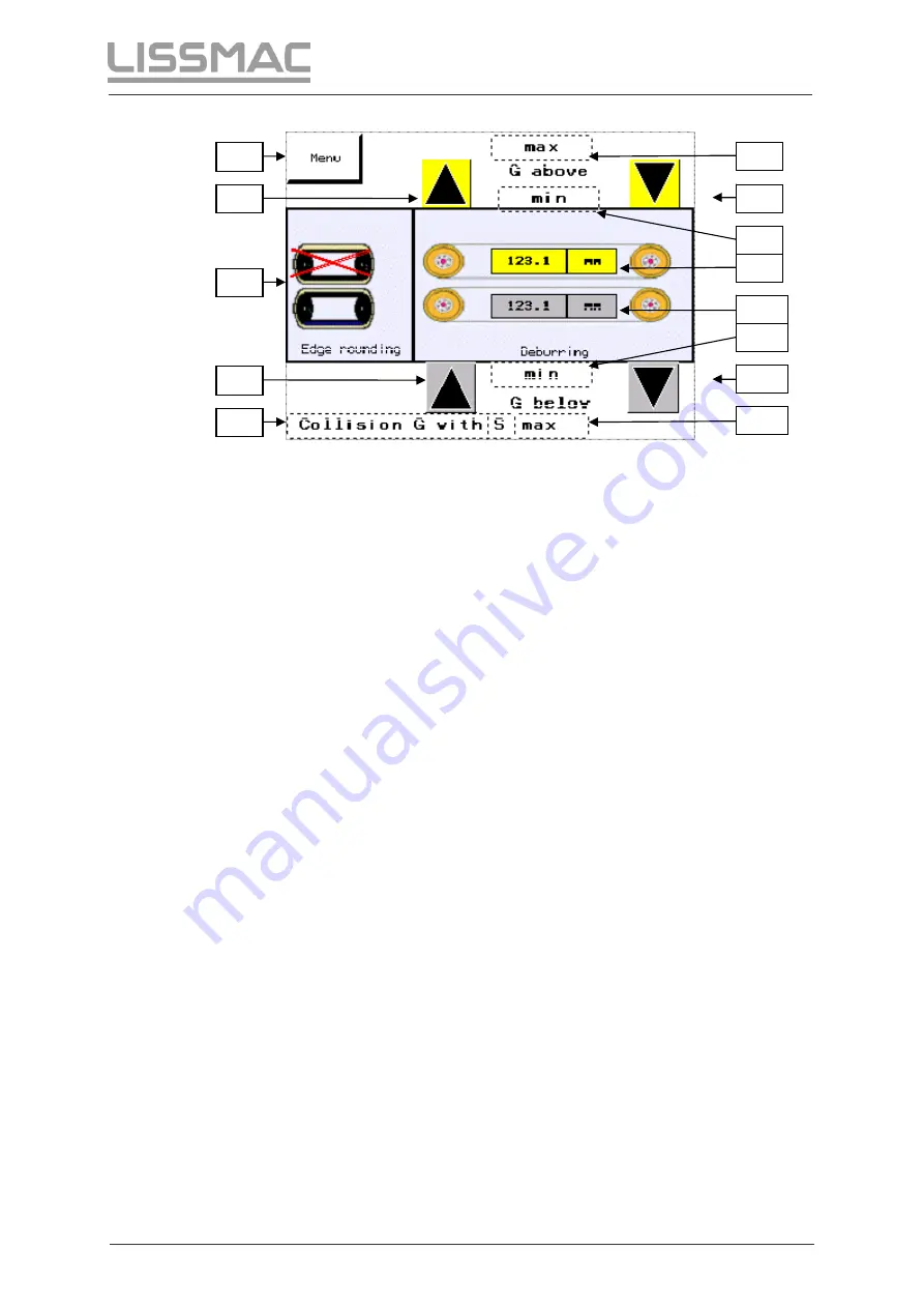
Abb. 30: 

Display – lower G-unit  


Menu (see 5.3.2) 

Button for moving the upper G unit upwards. 

Button for changing to lower S unit. 

Button for moving the lower G unit upwards. 

Display only appears if the lower G axle and lower S axle have 
collided. 

Display appears if the maximum position of the upper G unit has 
been reached. 

Button for moving the upper G unit downwards. 

Display appears if the minimum position of the upper G unit has 
been reached. 

Current position of the upper G axle. 

10  Current position of the lower G axle. 

11  Display appears if the minimum end position of the lower G unit 

has been reached. 

12  Button for moving the lower G unit downwards. 

13  Display appears if the maximum end position of the lower G unit 

has been reached. 


8

13

12

11

10

Summary of Contents for SBM-L 1000 G1S2 ALU MIX

Page 1: ...TING MANUAL GRINDING MACHINE SBM L 1000 G1S2 ALU MIX SBM L 1500 G1S2 ALU MIX LISSMAC Maschinenbau GmbH Lanzstrasse 4 D 88410 Bad Wurzach Telefon 49 0 7564 307 0 Telefax 49 0 7564 307 500 lissmac lissm...

Page 2: ......

Page 3: ...Maschinenbau GmbH Lanzstra e 4 D 88410 Bad Wurzach Telephone 49 0 7564 307 0 Fax 49 0 7564 307 500 E mail lissmac lissmac com Web www lissmac com The dissemination or duplication of this operating ma...

Page 4: ...ial types of dangers 12 2 7 1 Electric power 12 2 7 2 Dust 12 2 7 3 Fire hazard 12 2 7 4 Explosion hazard 13 2 8 Symbols on the machine 14 3 Product description 16 3 1 Appropriate usage 16 3 2 Technic...

Page 5: ...ture lights 49 5 6 Switching machining material 49 6 Changing abrasives 50 6 1 Replacing G units grinding belts 50 6 1 1 Removing upper and lower G units grinding belt 50 6 1 2 Replace the sliding blo...

Page 6: ...68 7 2 6 Replacing the V belt on the back of the S unit 69 7 2 7 Tensioning the V belt on the back of the S unit 70 7 3 Lubrication points Hydraulic oil 71 7 3 1 Left guide shafts lubrication points 7...

Page 7: ...e machine must have read and understood this operating manual The operating manual is to be supplemented by directives for accident prevention and environmental protection according to national requir...

Page 8: ...tuation is not avoided fatal or serious injuries will result CAUTION This signal word signifies a dangerous situation If the situation is not avoided medium to slight injuries will result NOTE This si...

Page 9: ...l who only work occasionally on the machine e g for changeovers and service The operating manual is to be kept permanently at the machine location and easily accessible Perform checks for safe and haz...

Page 10: ...ns in the operating manual Only use the provided attachment points for the load carrying equipment Only use suitable transport vehicles with sufficient load capacity Reliably secure the machine during...

Page 11: ...disconnect the machine and the extraction system from the mains supply Before cleaning with cleaning agents close all openings with suitable materials in which no water or cleaning agent can penetrate...

Page 12: ...uminium dust If carcinogenic substances are released during grinding e g with stainless steel the exhaust system must be operated with an absolute filter Comply with operating manual for dust extracti...

Page 13: ...losive gas can be produced from corrosion 2 7 4 2 Division of zones The extraction of the aluminum or steel dust with suitable extraction systems see 2 7 2 and performance of the cleaning intervals se...

Page 14: ...ad the operating manual and follow the information in the operating manual Wear protective gloves when placing and removing workpieces Wear hearing protection when working on the machine Wear safety g...

Page 15: ...Safety Grinding Machine SBM L 1000 1500 G1S2 ALU MIX 15 Notes...

Page 16: ...ess steel These materials may not be machined simultaneously This machine may only be used as a system with a wet dust extractor provided for it and which is approved Always note the danger of explosi...

Page 17: ...2 6 kW 3 kW 3 6 kW Grinding motor speed 2845 RPM 3460 RPM 2875 RPM 3460 RPM Grinding motor voltage 400 V 480 V 400 V 480 V Grinding motor power consumption 4 8 A 4 6 A 6 25 A 6 2 A Running speed of a...

Page 18: ...g otherwise required 10 40 C air conditioning heating otherwise required Humidity 5 95 no condensation 5 95 no condensation Emission noise pressure level at operator s place average value since it dep...

Page 19: ...Grinding Machine SBM L 1000 1500 G1S2 ALU MIX 19 3 3 Type plate Abb 1 Type plate 1 Name of machine 2 Serial number of machine 3 Connection values and weights The type plate is located on the back of t...

Page 20: ...1 Control panel with selection switches 2 Display control element 3 Upper device door 4 Conveyor belt for input of workpieces 5 Safety shut off bar 6 Adjustable machine foot 7 Support for transport w...

Page 21: ...ntire machine 4 EMERGENCY STOP switch for immediate shutdown of the entire machine 5 Type plate 6 Ventilation grate on switching cabinet 7 Electrical connection 8 Optional interface 9 Lower device doo...

Page 22: ...5 Machining unit top 1 Grinding belt cover 2 Grinding belt tensioning lever 3 Conveyor belt for input of workpieces 4 Safety shut off bar 5 Belt roller 6 Locking lever Abb 6 Machining unit bottom 1 S...

Page 23: ...tch 3 Key switch for setup function 4 Acknowledge EMERGENCY STOP 5 Display phase sequence incorrect 6 Material exchange switch 7 All motors OFF ON 8 EMERGENCY STOP 9 Button for override of door during...

Page 24: ...side SBM L 1000 1500 G1S2 ALU MIX 60 1 Hand wheel for moving lower S unit 2 Hand wheel for adjusting sheet thickness 3 Hand wheel for moving upper S unit 4 Gear selector lever NOTE Operating the hand...

Page 25: ...brought under the feed roller on the conveyor belt 5 and transported between the machining units The machining units can be positioned along with the feed roller 2 using the sheet thickness adjustment...

Page 26: ...uched The electrical contacts with magnetic holding of the interlock 2 and 4 on the front of the machine and 5 and 7 on the back of the machine hold the flaps closed and shut the machine down if the f...

Page 27: ...orklift there are appropriate supports 3 built in under the grinding machine for tightening torques see 8 3 WARNING Heavy loads Injury from falling parts Do not stop under the lifted machine Only use...

Page 28: ...ment points or lift by the two supports with the forklift Remove the packaging from the machine Set up the machine on a fortified level floor with at least 2 5 t load carrying capacity Use the machine...

Page 29: ...nit selection switch 3 Key switch for setup function 4 Acknowledge EMERGENCY STOP 5 Display phase sequence incorrect 6 Material exchange switch 7 All motors OFF ON 8 EMERGENCY STOP 9 Button for overri...

Page 30: ...both G units are selected Both drives for the upper and lower G units are switched on Position 4 Here the lower G unit is selected Only the lower G unit is running The drive of the upper G unit is swi...

Page 31: ...this position both S units are selected Both drives for the upper and lower S units are switched on Position 4 Here the lower S unit is selected Only the lower S unit is running The drive of the upper...

Page 32: ...otary switch 2 5 2 4 Setup function with key switch Abb 16 Setup function 1 Hydraulic belt tensioner button 2 Key switch for setup function 3 Button Acknowledge EMERGENCY OFF Turn and hold key switch...

Page 33: ...Also the following values are displayed 3 Upper G axle Value corresponds to the current position in mm 4 Lower G axle Value corresponds to the current position in mm 5 Sheet thickness Value correspon...

Page 34: ...2 Menu Abb 18 Menu On the Menu screen the following menu items are available 1 Operation see 5 3 1 2 Language see 5 3 3 3 Operating hours Date Time see 5 3 4 4 Contact see 5 3 5 5 Cleaning see 5 3 6...

Page 35: ...5 3 4 Operating hours Date Time Abb 20 Operating hours Date Time 1 Back button 2 Button Set date time see 5 3 4 1 3 Operating hours counter 4 Date display 5 Time display 6 Display Screen saver turns...

Page 36: ...e 3 When the respective number field is touched a field appears in which the desired value can be entered 4 When the synchronisation button is pushed the values form the number fields 3 are transferre...

Page 37: ...is cleaned before reaching the cleaning interval If the time until Cleaning interval reached is less than 5 minutes every 30 seconds the display Clean machine is shown see 5 3 6 2 However processing...

Page 38: ...ALU MIX 38 5 3 6 3 Resetting the cleaning interval Abb 25 Cleaning 3 1 Back button 2 Machine cleaned Pushing this button resets the cleaning interval display 5 3 7 Alarms Abb 26 Alarms 1 Error message...

Page 39: ...display functions switch to the function pertaining to that gear Abb 28 Gear selector lever 1 Lower S unit Lower G unit see 5 3 9 1 2 Upper and lower S unit Upper and lower G unit see 5 3 9 2 3 Upper...

Page 40: ...Abb 29 Display Lower S unit 1 Menu see 5 3 2 2 Current position of lower S unit 3 Display only appears if the lower G axle and lower S axle have collided 4 Display appears if minimum end position has...

Page 41: ...pears if the maximum position of the upper G unit has been reached 7 Button for moving the upper G unit downwards 8 Display appears if the minimum position of the upper G unit has been reached 9 Curre...

Page 42: ...ion Grinding Machine SBM L 1000 1500 G1S2 ALU MIX 42 5 3 9 2 Display of upper and lower S unit Upper and lower G unit Abb 31 Display Upper and lower S unit Abb 32 Display Upper and lower G unit see 5...

Page 43: ...Operation Grinding Machine SBM L 1000 1500 G1S2 ALU MIX 43 5 3 9 3 Display Upper S unit Upper G unit Abb 33 Display Upper S unit Abb 34 Display Upper G unit see 5 3 9 1...

Page 44: ...eet thickness 1 Menu see 5 3 2 2 This button switches to the G unit 3 Display only appears if the S axle is located at the upper end point 4 Display appears if maximum sheet thickness has been reached...

Page 45: ...display see 5 3 9 4 2 Set sheet thickness joystick 3 Sheet thickness setting gear selection lever NOTE Workpieces remaining in the machine Damage to the machine Ensure that no workpieces are in the m...

Page 46: ...hecked for damage visual inspection Place the main switch on the back of the machine into the On position Make sure that all malfunctions are corrected Ensure that both EMERGENCY STOP buttons are dise...

Page 47: ...ossible machining of all edges always place the workpiece with its straight edges diagonal to the grinding belt if possible NOTE Minimum dimensions of the workpiece Damage to the machine the workpiece...

Page 48: ...oved from pipes Not intended use especially includes the machining of composite materials in which both aluminium and steel dust are simultaneously generated Abb 40 Connecting the wet separator 1 Dust...

Page 49: ...e material switch and the fixed piping are not matched to each another 5 5 2 Fault lamp see 3 4 Grinding machine structure lights The material switch and the extraction system are not connected to one...

Page 50: ...The upper and lower G units must be moved completely into their end positions to change the grinding belts For the upper G unit the sheet thickness must additionally be moved to zero see display Chan...

Page 51: ...ing block belts the safety plate 1 must first be removed on the respective G unit and replaced after the work is completed Abb 42 Upper G unit with mounted safety plate Abb 43 Replacing sliding blocks...

Page 52: ...be removed on the respective G unit and replaced after the work is completed Abb 44 Upper G unit with mounted safety plate Abb 45 Sliding block belt 1 Sliding block belt tensioning roller 2 Counter n...

Page 53: ...lection roller to the maximum end position and fix with the screw fasteners 4 for tightening torque see Chapter 8 3 Tighten the sliding block belt with the tensioning roller 1 using the tensioning bol...

Page 54: ...6 1 6 Align grinding belts Abb 48 Adjust running of the belt 1 Left adjustment screw 2 Right adjustment screw Start grinding units and observe the belt running For this turn the S unit selection swit...

Page 55: ...e abrasive belts To do this note the wear 1 and 2 shown in the display and later apply the value to the abrasive belt Since the abrasive belts depend on the operating direction the direction of the ab...

Page 56: ...ly be moved to zero see display Changing the abrasive belt is shown on the upper S unit Changing the abrasive belt in the lower S unit is identical Abb 50 Access to S unit NOTE In order to move the S...

Page 57: ...sioned actuation is carried out from the operating unit Abb 51 Hydraulic belt tensioner 1 Rotary switch for hydraulic belt tensioner Set the rotary switch of the hydraulic belt tensioner 1 from positi...

Page 58: ...the S unit abrasive belt The hydraulic belt tensioner has an automatic shutoff using the end switch This ensures that the abrasive belts are always correctly tensioned Abb 54 Hydraulic belt tensioner...

Page 59: ...ive belts reset the to the noted wear value on the abrasive belt or measure according to 6 2 8 Abb 55 Wear display Display in operation mode 5 3 1 1 Wear display on top S unit 2 Wear display on bottom...

Page 60: ...for wear display 5 Base plate for upper abrasive belt 6 Base plate for lower abrasive belt Both abrasive belts can be measured independently of one another Measuring the wear on the upper abrasive be...

Page 61: ...utton down see 3 6 Control elements on the machine and move with the S unit joystick until the wear display is at zero Bring lever 2 or lever 4 into the initial position After the wear measurement the...

Page 62: ...ing hood screw fastener 2 Covering hood 3 Belt tensioner grinding belt drive screw fastener 4 Upper tensioning bolt counter nut 5 Lower tensioning bolt counter nut 6 Grinding belt drive tensioning rol...

Page 63: ...1S2 ALU MIX 63 7 1 3 Putting on the poly V belt Abb 58 Putting on the poly V belt 1 Poly V belt Put on new poly V belt NOTE To prevent damage to the poly V belt and to the belt drive make sure that th...

Page 64: ...rive screw fastener 4 Upper belt tensioner counter nut 5 Lower belt tensioner counter nut Slide the tensioning roller 1 with the counter nut 4 until the poly V belt is pre tensioned The poly V belt 2...

Page 65: ...en screw fasteners 2 Pull back belt tensioner 3 Remove toothed belt 1 and check the belt pulleys for wear Put new toothed belt 1 into place Slide belt tensioner 3 in the direction of the toothed belt...

Page 66: ...port bar Abb 61 Remove support bar 1 Support bar 2 Screw fasteners Unscrew the screw fasteners 2 Remove the support bar 1 7 2 2 Removing the V belts Abb 62 Removing the V belts 1 Drive motor screw fas...

Page 67: ...ALU MIX 67 7 2 3 Installing the V belt NOTE Always replace the V belts in pairs If V belts are replaced individually secure drive is no longer possible Abb 63 Installing the V belt 1 Inner V belt 2 Ou...

Page 68: ...nut 2 to tension the drive motor V belt pulley 4 until the V belt can still be pushed in about 1 cm on its longest segment Tighten the screw fasteners 1 with the tightening torque see Chapter 8 3 7 2...

Page 69: ...airs If V belts are replaced individually secure drive is no longer possible Abb 66 Outer V belt 1 drive motor 2 fastening nuts 3 V belts 4 Counter nuts 5 Counter nut 6 Tensioning bolt Loosen fastenin...

Page 70: ...rive motor 2 Fastening nuts 3 V belts 4 Counter nut 5 Counter nut 6 Tensioning bolt Put new V belt 3 into place Turn counter nut 4 back Use counter nut 5 to tension the drive motor 1 until the V belt...

Page 71: ...hafts lubrication points 1 Upper left lubrication points 2 Lower left lubrication points Lubrication points 1 and 2 according to the service schedule 7 3 2 Right guide shaft lubrication points Abb 69...

Page 72: ...Plugs Remove plugs 2 from the cover guide shafts Move the G unit so far in the direction of the end position until the lubricating nipple 1 can be seen in the opening Lubricate point 1 according to t...

Page 73: ...e minimum and maximum markings If the hydraulic oil level is too low the hydraulic belt tensioner for the S unit cannot work correctly and belt tension is not assured Abb 72 Hydraulic oil level 1 Hydr...

Page 74: ...ap 2 The grinding dust may not come into contact with ignition sources e g fire Remove all dust deposits and other residues work pieces tool wear sheet metal auxiliary materials etc from the interior...

Page 75: ...e machine must be thoroughly cleaned This should prevent dust collections from forming These daily cleaning tasks of the machine is to be recorded in writing in the cleaning record Machining of alumin...

Page 76: ...bricating nipple of the Flanged bearing see 7 3 4 daily once per shift every 8 hrs Changing the filter pad on the control cabinet weekly Check drive belts and deflection rollers for wear daily once pe...

Page 77: ...and ISO 4762 hexagon socket head screws as well as screws with analogous head strength for a friction coefficient of tot 0 12 Maximum tightening torque Maximum Ma in Nm Hexagon head screws hexagon soc...

Page 78: ...pushed in front or in back Disengage EMERGENCY STOP With synchronous operation acknowledge with an SBM GS EMERGENCY OFF to SBM GS Main switch set to 0 Set main switch to 1 Door contact switch defecti...

Page 79: ...e If malfunctions occur which cannot be remedied by the customer themselves contact the following customer service address LISSMAC Maschinenbau GmbH Lanzstra e 4 D 88410 Bad Wurzach Telephone 49 0 756...

Page 80: ...arts delivered to recycling and disposal The following parts of the machine contain environmentally hazardous substances Electronic components of the controls Gears lubricant Disconnect the machine fr...

Page 81: ...s Friction and overload couplings braking equipment Carbon brushes collectors Easily dissolvable rings External potentiometer and manual switching elements Fuses and lamps Auxiliary and operating mate...

Page 82: ......

Reviews: