background image

29

Operating and servicing your train set

Setting the Exploding Boxcar (continued)

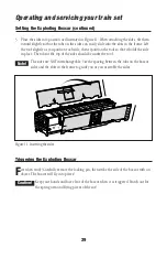
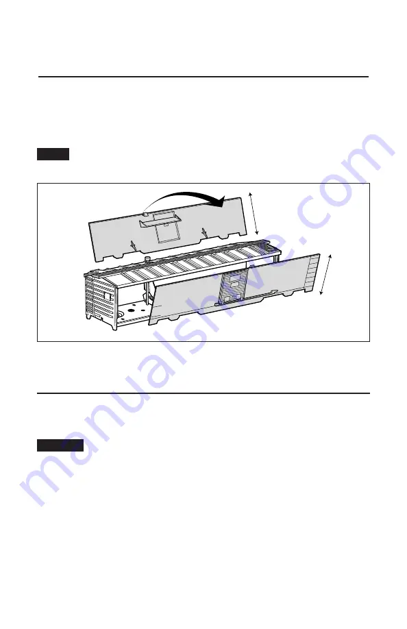
3. Place the sides into position as illustrated in Figure 11. When attaching the sides, tilt them

inward slightly so that the tabs on the sides can easily slide into the slots in the frame. Lift
the roof slightly as you position each side, then reposition the roof so that it holds the side
in place. The tabs at the top of the sides should be under the roof.

The sides are NOT interchangeable. Use the spacing between the tabs on the boxcar
sides and the slots in the frame to guide you as you assemble the sides.

Triggering the Exploding Boxcar

F

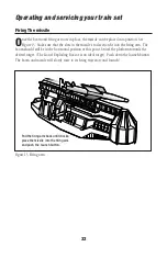
ire when ready! Carefully remove the locking pin, then strike the side of the boxcar with an
object. The boxcar will fly into pieces!

Keep your hands and face clear of the boxcar when it is triggered. Watch out for
the spring arm and flying pieces of the car!

Caution!

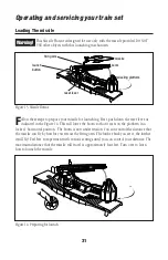
Figure 11. Inserting the sides

Note!

Summary of Contents for 2545WS N&W Space-Freight

Page 1: ...Lionel 2545WS N W Space Freight Owner s Manual Lionel 2545WS N W Space Freight Owner s Manual 73 1754 250 9 06 featuring and...

Page 2: ...ss Tether connection between locomotive and tender Operating headlight with directional back up light in tender Die cast metal locomotive body frame and trucks ElectroCoupler on rear of tender Tractio...

Page 3: ...n a round trip 15 TrainMaster Command Control operations TrainMaster Command Control operations 16 Operating your locomotive in the Command Control environment 16 CAB 1 Remote Controller commands 17 C...

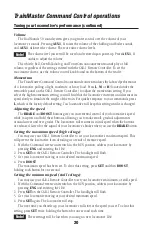
Page 4: ...throttle up TrainMaster Command Control operations To operate your locomotive in the Command Control environment you need a Command Base available separately 6 12911 and a CAB 1 Remote Controller ava...

Page 5: ...you control your locomotive s speed by varying track voltage with the transformer s throttle To increase the speed of the locomotive you increase track voltage To decrease the speed you decrease track...

Page 6: ...ontrol environment The headlight flickers as the locomotive searches for a signal from the Command Base When the locomotive has determined that a Command Base is not connected to the track the flicker...

Page 7: ...ansformer s DIRECTION button or interruptions in track power to get your locomotive moving in the desired direction 2 Slow the locomotive down without stopping reduce the throttle without turning off...

Page 8: ...gs the sounds of the railroad to your layout through high quality sound recordings of real locomotives When you operate your locomotive in the conventional environment you get realistic chuffing sound...

Page 9: ...tery installation RailSounds 5 0 sound system operations Installing the battery continued SIGNAL SOUNDS RAIL SOUNDS Body screws Front Body screws Volume control knob RailSounds switch Inside the tende...

Page 10: ...es 8 and 9 In the conventional environment you will experience several features of the RailSounds 5 0 sound system DynaChuff Your locomotive s speed automatically determines the level of chuffing soun...

Page 11: ...s through the Sound Activation Button s Do not bypass the buttons 11 LIONEL SOUND ACTIVATION BUTTON 1 2 POWER SUPPLY For AC transformers lacking a bell button For AC transformers lacking bell and horn...

Page 12: ...he state of the locomotive If the locomotive has been stopped for less than 15 seconds a short whistle blast triggers a please standby dialog If the locomotive has been stopped for longer than 15 seco...

Page 13: ...our transformer to begin the effect then press BELL a second time to discontinue the effect Squealing brakes Press the BRAKE button and listen for the squealing of the locomotive s brakes as the locom...

Page 14: ...er The actual dialog will vary Locomotive Commands Example dialog AUX1 2 Crew Can we go Tower No please standby AUX1 7 Tower Stand by for clearance Crew Roger Stopped 2 Crew Can we go Tower Roger you...

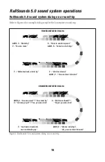
Page 15: ...ve s round trip AUX1 7 Stand by 7 You are clear 5 Slow to caution speed AUX1 5 Come to a full stop 7 Welcome back stand by 7 All clear ahead AUX1 7 You are clear inbound AUX1 2 Are we clear No stand b...

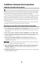
Page 16: ...power to go places but it doesn t tell you where to go or how fast to get there Operating your locomotive in the Command Control environment 1 Turn off track power and plug in the Command Base Be sure...

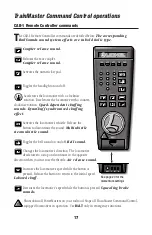
Page 17: ...es the locomotive s whistle Release the button to discontinue the sound Multiwhistle steam whistle sound Toggles the bell sound on and off Bell sound Changes the locomotive s direction The locomotive...

Page 18: ...commences Starts the RailSounds 5 0 sound system if the locomotive was previously shutdown Triggers the water pump sounds Activates Manual Chuff Mode see page 19 to set the chuff intensity manually Wa...

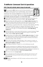
Page 19: ...ive The intensity of the chuff sounds does not vary with the throttle settings or the speed of the locomotive To set a constant chuff intensity get your locomotive moving then press AUX1 3 or AUX1 6 t...

Page 20: ...tive s speed while you press and hold these buttons allowing you to make small gradual adjustments around curves and over grades The locomotive will resume its initial speed when the buttons are relea...

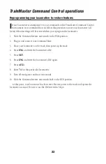
Page 21: ...switch on your locomotive to the PGM position 2 Place the locomotive on the track 3 Connect the Command Base and plug it in 4 Power up the track 5 Press ENG 6 Enter the unique ID Choose any number fr...

Page 22: ...everse unit switch to the PGM position 2 Plug in and connect your Command Base 3 Place your locomotive on the track then power up the track 4 Press ENG and enter the locomotive s ID 5 Press SET 6 Pres...

Page 23: ...gher speeds Smoke production is greatest at high voltages and when the locomotive pulls a heavy load When smoke production decreases add four to eight additional drops of smoke fluid When the smoke un...

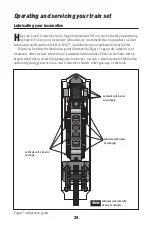
Page 24: ...that the lubrication points illustrated in Figure 5 appear dry lubricate your locomotive after you have removed any accumulated dirt and dust There are two basic rules to keep in mind when you are lu...

Page 25: ...connect to the motor brushes may have shifted during operation and need adjustment Straighten the wire brush shunts as in Figure 6 below making sure they do not contact each other or the motor casing...

Page 26: ...ve the three body screws 3 Lift the chassis away from the cab assembly being careful of the attached wires Locate and replace the expired lamp with Lionel part no 610 8047 300 4 Reassemble the cab to...

Page 27: ...heel 4 Reinstall and tighten the drive rod nut This service can also be performed by your authorized Lionel Service Center Note Figure 8 Traction tire replacement Operating and servicing your train se...

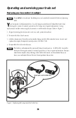
Page 28: ...sm is triggered to cause this car to explode When the mechanism is set keep your fingers out of the path of the metal arm The mechanism can go off at anytime Do not allow children to operate or set th...

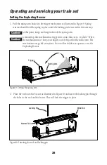
Page 29: ...the side in place The tabs at the top of the sides should be under the roof The sides are NOT interchangeable Use the spacing between the tabs on the boxcar sides and the slots in the frame to guide y...

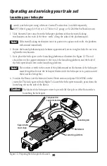
Page 30: ...tructure to the rear of the launching platform and the body of the helicopter should rest on the launching platform The notches or teeth in the center of the platform and on the bottom of the helicopt...

Page 31: ...he farther back you set it the farther it will fly Feel free to experiment with various settings until you can control your distance The maximum distance that the missile will travel is approximately...

Page 32: ...still be in the horizontal position at this point Swivel the platform towards the desired target The Lionel Exploding Boxcar is an ideal target Push down the launch button The boom and missile will s...

Page 33: ...adar antenna It is not necessary to remove this screw 3 Carefully remove the body by locating the four tabs that secure the body to the flatcar and gently bending them inward 4 Remove the expired lamp...

Page 34: ...fer to Figure 19 3 Lift away the body Be careful with the wires that attach the body to the frame 4 Carefully pull the expired lamp straight up and out of the socket then install the replacement bulb...

Page 35: ...the body to the frame 4 Follow the two wires from the expired lamp to their wire nut connections Unscrew the two wire nuts and separate the wires to free the lamp Push the expired light out through th...

Page 36: ...th your dated sales receipt and completed warranty information to the nearest Authorized Lionel Service Center Your nearest Lionel Service Center can be found by calling 1 800 4 Lionel or by accessing...

Reviews:

Related manuals for 2545WS N&W Space-Freight