background image

–     –

–     –

30

31

Resources

Support

For technical support, product documentation, application notes, regulatory 
guidelines and software updates, visit www.linxtechnologies.com

RF Design Services

For customers who need help implementing Linx modules, Linx offers 
design services including board layout assistance, programming, 
certification advice and packaging design. For more complex RF solutions, 
Apex Wireless, a division of Linx Technologies, creates optimized designs 
with RF components and firmware selected for the customer’s application. 
Call +1 800 736 6677 (+1 541 471 6256 if outside the United States) for 
more information.

Antenna Factor Antennas

Linx’s Antenna Factor division has the 
industry’s broadest selection of antennas 
for a wide variety of applications. For 
customers with specialized needs, custom 
antennas and design services are available 
along with simulations of antenna performance to speed development. 
Learn more at www.linxtechnologies.com.

by

Reflow Temperature Profile

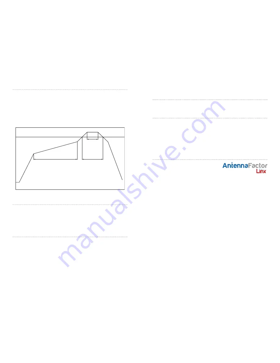
The single most critical stage in the automated assembly process is the 
reflow stage. The reflow profile in Figure 36 should not be exceeded 
because excessive temperatures or transport times during reflow will 
irreparably damage the modules. Assembly personnel need to pay careful 
attention to the oven’s profile to ensure that it meets the requirements 
necessary to successfully reflow all components while still remaining 
within the limits mandated by the modules. The figure below shows the 
recommended reflow oven profile for the modules.

Shock During Reflow Transport

Since some internal module components may reflow along with the 
components placed on the board being assembled, it is imperative that 
the modules not be subjected to shock or vibration during the time solder 
is liquid. Should a shock be applied, some internal components could be 
lifted from their pads, causing the module to not function properly.

Washability

The modules are wash-resistant, but are not hermetically sealed. Linx 
recommends wash-free manufacturing; however, the modules can be 
subjected to a wash cycle provided that a drying time is allowed prior 
to applying electrical power to the modules. The drying time should be 
sufficient to allow any moisture that may have migrated into the module 
to evaporate, thus eliminating the potential for shorting damage during 
power-up or testing.  If the wash contains contaminants, the performance 
may be adversely affected, even after drying.

Preheat:

150 - 200°C

Peak: 240+0/-5°C

25 - 35sec

220°C

2 - 4°C/sec

120 - 150sec

2 - 3°C/sec

60 - 80sec

30°C

Figure 36: Maximum Reflow Temperature Profile

Summary of Contents for R4 Series

Page 1: ...R4 Series GPS Receiver Module Data Guide...

Page 2: ...egulatory certification and warranty Customers may use our non Function Modules Antenna and Connectors as part of other systems in Life Safety Situations but only with necessary and industry appropria...

Page 3: ...us RF or GPS experience Features SiRF Star IV chipset Built in jammer remover High sensitivity 160dBm 48 channels Fast TTFF at low signal levels Battery backed SRAM CGEE allows 3 day prediction No pro...

Page 4: ...Supply Operating Voltage VCC 3 0 3 3 3 6 VDC Supply Current lCC Peak 122 mA 1 Acquisition 56 mA 1 Tracking 33 mA 1 Hibernate 0 43 mA 1 Backup Battery Voltage VBAT 2 0 6 0 VDC Backup Battery Current IB...

Page 5: ...satellite transmits low power radio signals which contain three different bits of information a pseudorandom code identifying the satellite ephemeris data which contains the current date and time as...

Page 6: ...then outputs the data through a standard serial port using several standard NMEA protocol formats The GPS core handles all of the necessary initialization tracking and calculations autonomously so no...

Page 7: ...RFIN line This bead prevents the RF from getting into the power supply but allows the DC voltage onto the RF trace to feed into the antenna A series capacitor inside the module prevents this DC volta...

Page 8: ...have selectable baud rates it s recommended that SiRF Binary use 115 200bps For a detailed description of the SiRF Binary protocol see the SiRF Binary Protocol Reference Manual available from SiRF Tec...

Page 9: ...rential GPS SPS Mode fix valid 3 5 Not supported 6 Dead Reckoning Mode fix valid Figure 9 Position Indicator Values GLL Geographic Position Latitude Longitude Figure 10 contains the values for the fol...

Page 10: ...s Channel 4 Range 00 to 90 Azimuth 077 degrees Channel 4 Range 00 to 359 SNR C No 46 dB Hz Channel 4 Range 00 to 99 null when not tracking Checksum 73 CR LF End of message termination 1 Depending on t...

Page 11: ...Figure 17 outlines the message identifiers supported by the module Serial Data Structure Name Example Description Start Sequence PSRF Message ID MID Message Identifier consisting of three numeric cha...

Page 12: ...alization This command is used to initialize the receiver with the current position in X Y Z coordinates clock offset and time enabling a faster fix Increased receiver sensitivity and the removal of S...

Page 13: ...ssages may be polled once or setup for periodic output Checksums may also be enabled or disabled depending on the needs of the receiving program NMEA message settings are saved in battery backed memor...

Page 14: ...ault value of 96000 is used Figure 24 ResetCfg Values ResetCfg Values Hex Description 0x01 Hot Start All data valid 0x02 Warm Start Ephemeris cleared 0x04 Cold Start Clears all data in memory 0x08 Cle...

Page 15: ...e is also included for use with a PC running custom software or the included development software The Master Development System software enables configuration of the receiver and displays the satellit...

Page 16: ...r the module A ground plane as large and uninterrupted as possible should be placed on a lower layer of your PC board opposite the module This plane is essential for creating a low impedance return fo...

Page 17: ...ackage that supports hand and automated assembly techniques Since the modules contain discrete components internally the assembly procedures are critical to ensuring the reliable function of the modul...

Page 18: ...irreparably damage the modules Assembly personnel need to pay careful attention to the oven s profile to ensure that it meets the requirements necessary to successfully reflow all components while sti...

Page 19: ...stomer including without limitation breach of contract breach of warranty strict liability or negligence Customer assumes all liability including without limitation liability for injury to person or p...

Reviews: