background image

April  27, 2004 Manual Version 1.01

4.2

Stroke

Mode Single Stroke

Drive

Speed
Stroke
Speed

SPM

SPM

0
0

Current Status

TONNAGE
MONITOR

EXIT

0

0

Program/Run Switch

TOP

CHANGE
VIEW

REVERSE
TONNAGE

GRAPH

View

Peak
Forward Tonnage

Total

82.8 

Tons

HIGH  150%

LOW      0%

CH1 - LEFT FRONT

HIGH LIMIT:

18.7


Tons

LOW LIMIT:            16.0

STATUS: OK

HIGH  150%

LOW      0%

CH2 - RIGHT FRONT

HIGH LIMIT:           25.0

20.4


Tons

LOW LIMIT:            16.0
STATUS: OK

HIGH  150%

LOW      0%

CH3 - LEFT REAR

HIGH LIMIT:           20.0

19.5


Tons

LOW LIMIT:            12.0

STATUS: OK

HIGH  150%

LOW      0%

CH4 - RIGHT REAR

HIGH LIMIT:           30.0

27.9


Tons

LOW LIMIT:            20.0
STATUS: OK

Module Status:  OK

CHANGE
HIGH LIMIT

25.0

LOW LIMITS
ON/OFF

BYPASS
ON/OFF

CONFIGURE

AUTO-SETUP

CHANGE
LOW LIMIT

RESET
FAULT

a

b

c

d

e

f

g

h

i j

Last Stop

Program/Run Switch

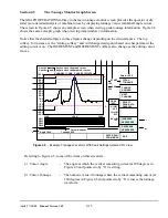
Section 4.2

Main Tonnage Monitor Screen

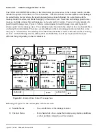
The TONNAGE MONITOR softkey in the Main Menu provides access to the tonnage monitor module
installed to operate with either two or four channels.  This screen shows the maximum forward tonnages
recorded during the last stroke, the description and status of each channel, the overall status of the
tonnage monitor module, and limits that apply to the current view.  Peak forward tonnage, peak reverse
tonnage, and data window forward tonnages can be selected for viewing.  Figure 4.2 is an example of a
peak forward tonnage view, Figure 4.3 shows a data window forward tonnage view, and Figure 4.4
shows a peak reverse tonnage view.  Two channel screens look much the same but have no channel three
or channel four information. There are several softkeys on the main tonnage monitor screen that come
into play at various times.  The softkeys and other functions of this screen are discussed in the following
sections.  In the following screens, softkeys that are shaded may not always be present and may say
different things depending on the circumstances.

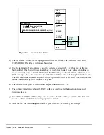
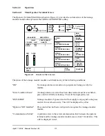
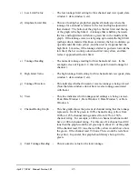
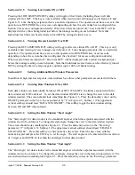
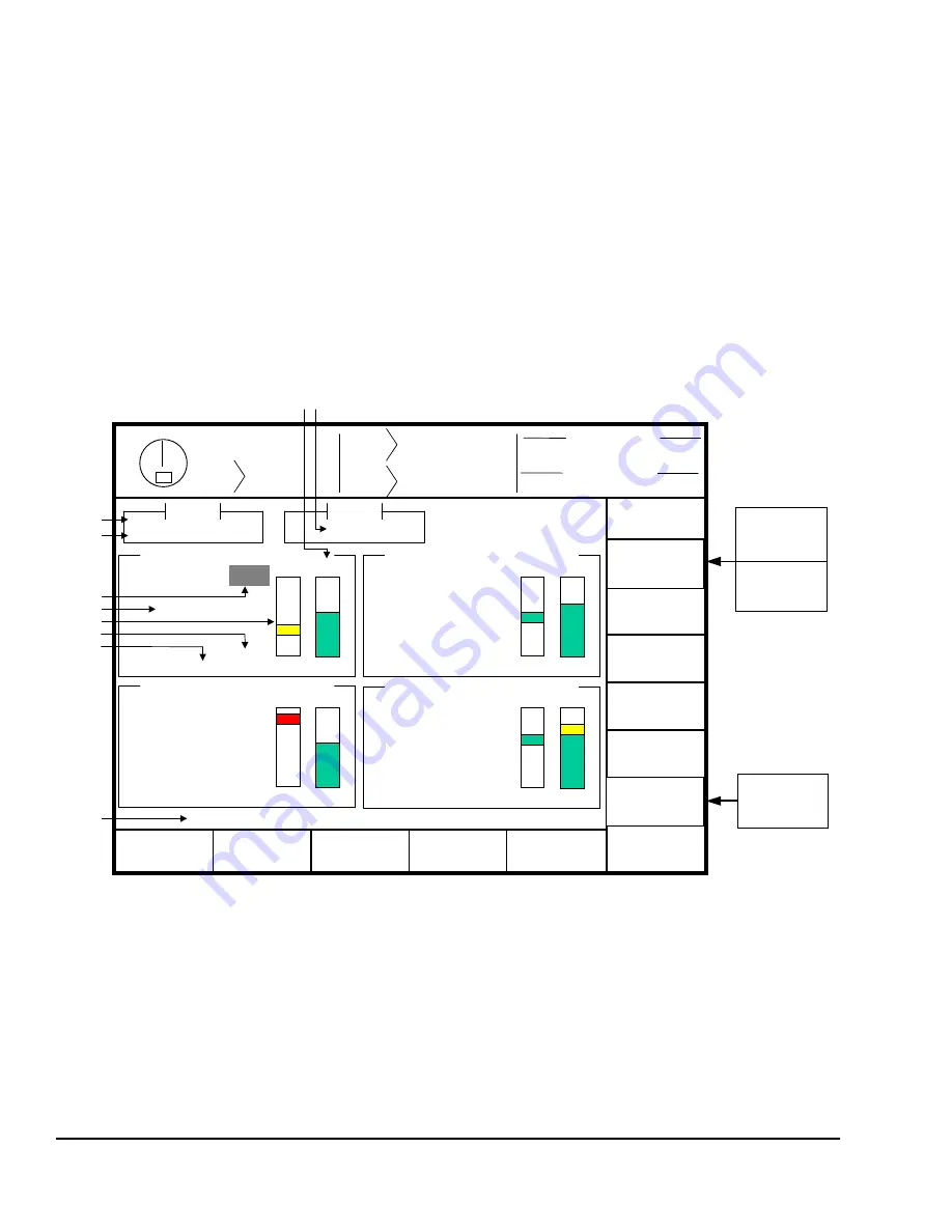
Referring to Figure 4.2, the various parts of this screen are:

a) Module Status 

-

The overall status of the tonnage monitor.  

b) Channel Status

-

Each channel also has a status that indicates any alarms conditions
or other problems related to just that channel.

Figure 4.2

  - Example Peak Forward Tonnage View

Summary of Contents for OmniLink II

Page 1: ...OmniLink II Press Automation Control TONNAGE ANALOG SIGNAL MONITOR OPERATING MANUAL Version 1 01 R Link Electric Safety Control Co 444 McNally Drive Nashville TN 37211 PH 615 833 4168 FAX 615 834 1984 ...

Page 2: ...otal Tonnage 3 1 Section 3 1 3 Reverse Tonnage 3 3 Section 3 2 Data Windows 3 4 Section 3 2 1 Data Window On Angle 3 4 Section 3 2 2 Data Window Off Angle 3 5 Section 3 3 Limits 3 6 Section 3 3 1 Machine Rating Limit 3 6 Section 3 3 2 Low Limits 3 6 Section 3 3 3 High Limits 3 6 Section 3 3 4 Reverse Limits 3 6 Section 3 3 5 Total Tonnage Limit 3 7 Section 4 Operation 4 1 Section 4 1 Main Operator...

Page 3: ...n 4 4 2 Channel Errors 4 13 Section 4 4 3 Resetting Errors 4 14 Section 4 5 The Tonnage Monitor Graph Screen 4 15 Section 4 5 1 Viewing the Graph 4 19 Section 4 5 1 1 Graph Start Angle 4 19 Section 4 5 1 2 Graph End Angle 4 19 Section 4 5 1 3 Entering Pan Zoom Mode 4 20 Section 4 5 1 4 N A 4 20 Section 4 5 1 5 Selecting the Channel 4 20 Section 4 5 2 Graphically Setting Values 4 20 Section 4 5 3 N...

Page 4: ...s 7 3 Section 7 2 1 C Frame Machines 7 3 Section 7 2 2 Straight Side Machines 7 3 Section 7 3 Strain Gauge Mounting 7 7 Section 7 3 1 Direct Machine Mounting 7 7 Section 7 3 2 Intermediate Weld Pad Mounting 7 8 Section 7 4 Strain Gauge Wiring 7 9 Section 7 5 Installation Procedure 7 10 Section 7 6 Configuring Control 7 12 Section 8 Calibration 8 1 Section 8 1 Dynamic Calibration with Load Cells 8 ...

Page 5: ...April 27 2004 Manual Version 1 01 iv ...

Page 6: ...lows the module to instruct the OmniLink II control to Top Stop Cycle Stop or Cycle Stop and turn Off the hydraulic overload outputs depending on the present stroking mode and the type of tonnage alarm that has occurred d Within the working portion of the stroke tonnage limits for each job can be set for the maximum allowable forward tonnage High Limit minimum required forward tonnage Low Limit an...

Page 7: ...April 27 2004 Manual Version 1 01 1 2 ...

Page 8: ...he name of the value to be changed It may also simply say CHANGE NUMBER In any case hit this softkey to enter numeric input mode The editing cursor will change to a rectangle around the parameter to be edited c Use the numeric keypad to input the new number desired for the parameter d Press the ENT key to finish Note that moving off the parameter with the arrow keys or hitting the EXIT key will ab...

Page 9: ... be edited depending on where it is in the screen Hit the SELECT LETTER softkey to place that letter at the text cursor In the example above the text cursor is on the T in This and would be replaced with an A The text cursor will automatically move to the right when a letter is selected Note that numerals can be entered directly with the numeric keypad e The SPACE softkey can be used to enter a sp...

Page 10: ... the Key Only mode has the advantage of being easy to use it does have a disadvantage This mode cannot give a particular user access to only some of the restricted items When operating in this mode any user with the RUN PROG key will have access to all of the restricted items Section 2 2 2 Key or Password Mode The key or password mode allows for either of two means to gain access to the restricted...

Page 11: ... and password In addition all restricted items would be assigned access to the setup personnel Section 2 2 4 Key and Password Mode The Key and Password mode requires the user to have the RUN PROG key user name and user password Operation is basically the same as the Password only mode except that in addition to entering the password the user must switch the RUN PROG key to the PROG position Sectio...

Page 12: ...RUN PROG key switch is located on the lower right side of the operator terminal This is a two position switch The key is removable in the RUN position only If the RUN PROG key switch is being used as a means to access the restricted items the switch must be turned to the PROG position When the RUN PROG key switch is switched to the PROG position the press will Top Stop and stroking will be prohibi...

Page 13: ... to the Quick Access screen The LOGOUT soft key legend will appear along the bottom of the screen If the operator presses this key he will log out He will no longer have access to the restricted items unless he repeats steps A through D In addition to the manual log out the system contains an automatic logout The intent of automatic log out is to reduce the possibility of users other than the inte...

Page 14: ...el through the stroke or data window data windows are discussed in section 3 2 In addition the tonnage monitor can show the tonnage waveform for a channel This waveform shows how the tonnage varies with press crankshaft angle Section 3 1 2 Total Tonnage In addition to recording the maximum tonnage measured for each channel the tonnage monitor module calculates and records the instantaneous summati...

Page 15: ...the total force depends on the amount of force exerted at any specific position If the die described in the previous example had punches of different lengths as shown in Figure 3 3 the punches would not impact the material at the same position in the stroke The graph in Figure 3 4 shows that the punch on the left contacts the material first and exerts a total force of 100 tons at time t1 with 60 t...

Page 16: ...wn part of the cycle portions of the press frame stretch proportionally to the tonnage exerted In the case of a punch for example the tooling comes down and contacts the material The press frame starts stretching and this generates tonnage exerted on the material Finally the tonnage exerted is sufficient for the punch to break through the material and when it does the press frame tries to spring b...

Page 17: ...from a given start angle to a given end angle The tonnage graph in Figure 3 5A is for a two station die The first station cuts out the part local peak and the second station stamps a logo onto the part absolute peak Since the tonnage required to coin the logo is greater than the tonnage required to cut the part the local peak is not checked using a normal peak tonnage monitor The local peak could ...

Page 18: ...on 1 01 3 5 Section 3 2 2 Data Window Off Angle The Off Angle for a data window is the angle at which the setpoints for that data window stop being enforced For example in Figure 3 5 data window 1 has an off angle of 170 degrees ...

Page 19: ...ol in order to stop the process In stroking modes Inch and Timed Inch it is common the operate the press without material in the die during the setup operation In order to prevent unintended Top Stops the tonnage monitor module will automatically turn OFF the Low Limits during these modes The Low Limit for a particular channel can NOT be set greater than or equal to that channels High Limit Sectio...

Page 20: ...to height off the bottom of the stroke The machine rating is specified by the press manufacturer at a specific height off the bottom of the stroke typically 25 inches Above this height the total tonnage available is limited by the torque of the crankshaft and clutch and will decrease as the height off the bottom at which the tonnage occurs increases The machine rating derate table tells the tonnag...

Page 21: ...April 27 2004 Manual Version 1 01 3 8 ...

Page 22: ...re 4 1 provides the current status of the tonnage monitor module directly beside the TONNAGE MONITOR softkey The status of the tonnage monitor module could indicate any of the following conditions OK No tonnage alarms exist and no stop signals are being given by the module Error Condition Exists A tonnage alarm or an error has been detected and must be reset before press control will allow strokin...

Page 23: ...ard tonnages recorded during the last stroke the description and status of each channel the overall status of the tonnage monitor module and limits that apply to the current view Peak forward tonnage peak reverse tonnage and data window forward tonnages can be selected for viewing Figure 4 2 is an example of a peak forward tonnage view Figure 4 3 shows a data window forward tonnage view and Figure...

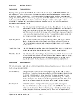
Page 24: ...xample screen of Figure 4 2 this is the peak forward tonnage for channel 1 f High Limit Value The high tonnage limit setting for this channel and view peak data window 1 data window 2 etc g Tonnage Direction This indicates whether forward or reverse tonnage is being viewed Note that data windows do not have reverse tonnage associated with them h View This line indicates which tonnages and settings...

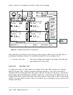
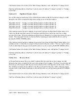
Page 25: ...OFF ON RESET ERROR CHANGE ON ANGLE CHANGE OFF ANGLE CHANGE HIGH LIMIT k l m GRAPH CONFIGURE AUTO SETUP Figure 4 3 shows a four channel screen when viewing data window tonnages Notice that the major difference between this screen and that of Figure 4 2 is the addition of three new parameters and the lack of a REVERSE TONNAGE softkey Referring to Figure 4 3 some additional settings in a data window ...

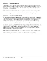
Page 26: ...nly one reverse limit for each channel Referring to Figure 4 3 an additional setting in the reverse tonnage view is n Reverse Limit Value The reverse tonnage limit setting for this channel Note that only peak tonnage has a reverse limit Section 4 2 1 Selecting a View As explained in section 3 2 data windows can monitor local peaks with a separate set of setpoints from the absolute peak Each set of...

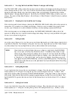
Page 27: ...lows the operator to change the view to peak reverse tonnage and settings This key is only available in the peak forward view as seen in Figure 4 2 as data windows do not have reverse tonnage associated with them When viewing peak reverse tonnages and settings the FORWARD TONNAGE softkey allows the operator to change the view to peak forward tonnage and settings This key is only available in the p...

Page 28: ...y is pressed a box will appear which allows the operator to enter a Percent Tolerance percent of machine rating of each channel which is applied to the peak tonnage recorded during the automatic setup process A tolerance from 1 to 30 percent of the channel rating is added to the highest tonnage recorded in the sixteen 16 successive strokes made in the auto setup mode in order to calculate the High...

Page 29: ...ndow Parameters In addition to high and low setpoints data windows have three other parameters associated with them Section 4 2 3 1 Turning Data Windows ON or OFF Each data window can individually be turned ON or OFF When OFF the limits associated with the data window are NOT enforced To set the data window ON OFF state change the view to the data window desired The screen should look something li...

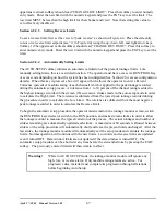
Page 30: ...th the exception of machine rating alarms In addition the tonnage monitor status will say Bypassed with a yellow background and Bypassed will be displayed with a yellow background just below the tonnage reading on each channel The module will always power up with Bypass turned OFF Section 4 2 5 The GRAPH OPERATIONS Softkey This softkey which appears only when the tonnage monitor has a valid wavefo...

Page 31: ...Status in the bottom of the Main Tonnage Monitor screen will indicate Tonnage Alarm The Present Running Status in the Press Control screen will indicate Tonnage Top Stop Section 4 3 2 High Peak Alarm A Channel Status message High Pk Alarm indicates that the maximum tonnage recorded during the last stroke exceeded the High Limit setting in Peak Tonnage If the tonnage monitor has been configured to ...

Page 32: ...g prevented until the alarm is reset by pressing the RESET ERROR softkey If the tonnage monitor has been configured to generate Cycle Stops for High Data Window alarms this condition causes an immediate stop signal to be provided to the press control This stop signal remains in effect and further stroking prevented until the alarm is reset by pressing the RESET ERROR softkey The Module Status in t...

Page 33: ...rred It is the only limit applied to the total tonnage and may or may not coincide with any channel alarm When the condition is detected on the total tonnage a Cycle Stop is provided to the press control This stop signal remains in effect and further stroking prevented until the alarm is reset by pressing the RESET ERROR softkey This alarm will only occur if the tonnage monitor is configured to de...

Page 34: ...20 and 250 degrees This could indicate an internal fault in the nonvolatile memory on the tonnage monitor board Mach Rate Error This indicates that the machine rating is not between 000 1 and 999 9 0001 9999 without decimal point and should only occur if there is an internal fault Dw Set Error This indicates an incorrect setting in the data window specified It would occur if the data window On Ang...

Page 35: ...nalog board Section 4 4 3 Resetting Errors If an alarm or error condition is detected a stop signal is provided to the press control and a RESET ERROR softkey provided in the Main Tonnage Monitor screen If configured to lock out access to resetting errors this softkey will appear only with the RUN PROG keyed selector switch in the PROG position In addition if access codes have been enabled see Sec...

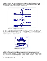
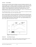
Page 36: ...rces by displaying tonnage versus crankshaft angle curves The screen in Figure 4 5 shows an example screen when viewing peak tonnage information Figure 4 6 shows the same example graph when viewing data window 2 information Notice that the shaded softkeys in these figures change depending on the circumstances The top softkey for instance is the editing softkey and will change description based on ...

Page 37: ... of setpoints are being viewed Peak Data Window 1 Data Window 2 Data Window 3 or Data Window 4 h Measuring Cursor The measuring cursor can be moved across the graph with the left and right arrow keys The Cursor Angle a and Cursor Tonnage b are updated as the cursor moves The cursor is extremely helpful for proper placement of data window start and end angles i Information Box The information box c...

Page 38: ...the maximum number is reached such as hitting an overload or stopping the press in the working portion of the stroke no further samples are stored l Increase Key The text of this key changes depending on which parameter the editing cursor not the measuring cursor is currently on In all cases however it will increment the value the editing cursor is on assuming the operator has access via RUN PROG ...

Page 39: ...en viewing peak tonnages Referring to Figure 4 6 some additional or different items on data window views are n Data Window Bars The lower portion of the graph display is used to indicate the active area of the data windows This graphically shows the position of the data window with respect to the tonnage waveform No bar appears for Peak Tonnage since it is always active The active area of a data w...

Page 40: ...n 4 5 1 1 Graph Start Angle The graph start angle the number directly under __START__ in Figure 4 5 specifies the crankshaft angle at which to begin displaying the tonnage waveform This should not be confused with the start angle of a data window The graph can not be set to start before the start of the working portion of the stroke see start of the sample window in machine settings configuration ...

Page 41: ...e editing cursor on the end angle parameter using the up and down arrow keys Then use the numeric keypad and press the ENT key Panning is the action of sliding the view window left or right on the graph Pres the PAN LEFT softkey to move the view of the graph to the left Likewise press the PAN RIGHT softkey to move the view of the graph to the right The graph will shift about 1 4 of the viewed widt...

Page 42: ...ormation box a softkey with the legend SET DW START ANG AT CURSOR will appear Pressing this key will set the data window start angle where the measuring cursor h in Figure 4 5 not the editing cursor is positioned at If the angle read out a in Figure 4 5 indicates 167 0 degrees and the SET DW START ANG AT CURSOR softkey is pressed the system will attempt to set the start angle for the currently sel...

Page 43: ...April 27 2004 Manual Version 1 01 4 22 Section 4 5 3 3 N A Section 4 5 3 4 N A Section 4 5 3 5 N A ...

Page 44: ...April 27 2004 Manual Version 1 01 4 23 Section 4 5 4 N A ...

Page 45: ...April 27 2004 Manual Version 1 01 4 24 ...

Page 46: ...rt Angle 280 Auto Zero End Angle 80 Peak High Limit Stop Type Cycle Stop DW High Limit Stop Type Cycle Stop Section 5 Configuration The configuration menus of the tonnage monitor module are accessed by selecting the CONFIGURE TON MON softkey in the Main Tonnage Monitor Screen with the RUN PROG keyed selector switch in the PROG position The operator terminal will request entry of the configuration ...

Page 47: ...outputs OR 2 3 control a mechanism that releases the hydraulic fluid in the overload system quickly Section 5 1 2 High Data Window Alarm Stop This parameter defines the type of stop signal sent to the press control when a High Alarm occurs in any data window View Data Window 1 4 The following settings are allowed Setting 000 This programs the tonnage monitor module to send a Top Stop signal to the...

Page 48: ...pansion or contraction of machine structural members and induce strains which can be detected by the tonnage monitor strain gauges mounted to the machine frame In addition strain gauges are manufactured with an inherent zero imbalance which can change if the gauge experiences any long term creep Slowly varying signals such as these are compensated by measuring the strain gauge signals while the ma...

Page 49: ...machine offsets and starts taking samples After it is reached each sample is examined in order to capture the peak tonnage for comparison with the limits in effect The determination of peak tonnage continues until the end of the working portion of the stroke End Sample Window Since this angle defines the start of the working portion of the stroke it must be set prior to the angle that tooling forc...

Page 50: ...e translation of rotary motion of the crankshaft to linear motion of the slide that changes depending upon crankshaft angle The constant torque of the clutch develops more downward force as the crankshaft angle travels from 90 degrees mid stroke to 180 degrees bottom If torque were the only limiting factor the press could deliver infinite tonnage at the bottom of the stroke However the elastic lim...

Page 51: ... occur if tonnage exceeds 36 of machine rating from 90 degrees to 119 degrees 40 from 120 to 129 degrees etc This feature is not required and may be bypassed by leaving 125 for all tonnage limits The 125 for all tonnage limits is the factory default setting However if a factory default setting is ever changed the maximum tonnage limit will be 115 for the setting that is changed For example the lim...

Page 52: ...ured each stroke Section 5 3 2 N A Static Calibration The STATIC CAL softkey causes the tonnage monitor to enter Static Calibration mode With the RUN PROG keyed selector switch in the RUN position it will initially zero any force present on the strain gauges After any offset force has been integrated to zero it will hold that offset value and begin displaying the present force tonnage applied to t...

Page 53: ...April 27 2004 Manual Version 1 01 5 8 Section 5 4 N A Reset Alarm Counters This selection displays the screen shown in Figure 5 6 Counters are reset with the softkeys shown ...

Page 54: ...toring 500 job setups Information on storing recalling or erasing job setups is in the OmniLink II manual The Tonnage Monitor Module will also store or recall all its pertinent data when the operator stores or recalls a job setup This includes all programmed information such as the low limits high limits reverse limits data window states ON OFF data window angles and reference waveforms The operat...

Page 55: ... stroke View Peak Tonnage be set for the approximate tonnage rating of the die The Low Limits will be automatically disabled in Inch or Timed Inch modes After the correct tonnage monitor settings are established for the die along all other OmniLink II settings the present settings should be stored under a job number and description for recall later ...

Page 56: ...age and Analog Signal Module Installation The OmniLink II Press Automation Control Tonnage and Analog Signal module can be used with the OmniLink II Press Automation Control system or with the OmniLink 5000 Press Control system This is illustrated in Figure 3 1 The Tonnage and Analog Signal module connects to either system via the high speed serial bus Section 7 1 1 Module Assembly Mounting and Wi...

Page 57: ...ner Switch must be in ON position switch up when device is last unit in the can bus chain Termination LED will light when switch is turned ON Switch must be in OFF position down when unit is NOT the last unit on the CAN bus Termination LEDwill be Off Figure 7 1 1 Module Faceplate Wiring The faceplate and wiring are shown in Figure 7 1 1 The following connections and operations must be done 1 Input...

Page 58: ...ounted in a location subject to shock and vibration shock mounts are required Either the card rack assembly can be shock mounted or the enclosure in which it is installed can be shock mounted In selecting the mounting location for the OmniLink II Press Automation Control Tonage and Analog Setup module the wiring connections for the unit should be considered After the mounting location has been det...

Page 59: ...r buckling bending on thin web side frames of some machines Figure 7 2 C Frame Machine Do not mount strain gauges near the curves at the front of the C frame The curvature of the frame produces nonlinear strain signals Also on presses with increased cross sections near the front of the frame avoid mounting sensors next to the change of cross section to avoid nonlinear strain signals The center por...

Page 60: ...ccess opening When holes are present in the desired upright mounting location avoid mounting strain gauges any closer than three diameters of the hole directly above or below the hole or any closer than one diameter of the hole to the side of the hole Don t mount strain gauges in recessed panel areas in uprights Figure 7 3 Straight Side Machine Stay away from corners of uprights as strain gauge mo...

Page 61: ... 01 7 6 Figure 7 4 Areas to Avoid on Straight Side Machines Do Not Mount in Cross Hatched Areas Figure 7 4 shows areas to avoid on uprights of straight side machines of tie rod construction The cross hatched areas should be avoided ...

Page 62: ...d Frame Straight Side Machines On solid frame straight side machines the preferred strain gauge mounting location is inside the windows under the ends of the crankshaft A strain gauge should be mounted on the inside face of each column forming the windows as shown in Figure 7 5 ...

Page 63: ... of straight side presses and C frame machines that are not inclined On inclined presses the scribe marks should follow the inclined angle 4 Place the hardened drill fixture provided with the direct mounting strain gauge kit in position adjacent to the scribed line and use a no 3 drill to drill a 5 8 deep hold through the center hole position of the drill fixture Tap the hole for a 1 4 x 28 thread...

Page 64: ... x 28 threads and bolt the alignment clamping fixture to the mounting area through the center hole Tack weld both sides of each intermediate pad to the mounting surface first then continuously weld the outer ends and sides of the intermediate pads to the mounting surface as shown in Figure 7 9 6 Remove the alignment clamping fixture Do not weld with the fixture removed 7 Bolt the LST 1000 strain g...

Page 65: ...control enclosure Once inside the enclosure route the strain gauge cables away from all other voltage sources as much as possible Run cables to the channel connectors on the front of the tonnage monitor module and cut the excess cable lengths off 3 Strip about 2 inches of cable insulation off of the braided wire shield Remove the four conductor wires from the shield taking care to leave the shield...

Page 66: ...nnage monitor module see Section 7 4 5 Power up the press control and use the press control configuration menus to turn the tonnage monitor option ON see Section 7 6 6 Exit to the Main Menu and select the TONNAGE MONITOR softkey Verify that the channel status indicates no errors for all channels 7 With the RUN PROG switch in the PROG position select the CONFIGURE TON MON softkey and the Configurat...

Page 67: ...ow limits for Peak Tonnage and all Data Windows Enter reverse limits The tonnage monitor is shipped from the factory with low high and reverse limits programmed If the installation procedure required the machine rating to be changed these limits may no longer be acceptable and could generate an error condition ...

Page 68: ...NE PARAMETERS The Machine Parameters menu will appear 5 Select the FACTORY CONFIG softkey The Factory Parameters menu will appear 6 Position the cursor onto the parameter Tonnage Monitor use the numeric keypad to change the entry from 000 OFF to 001 ON and press ENT The Configuration Code gives limited access to change parameters in this screen Only three parameters that can be changed with the Co...

Page 69: ...April 27 2004 Manual Version 1 01 7 14 ...

Page 70: ...machine must be cycled so that the slide strikes the load cells at the bottom of the stroke to generate the load Hydraulic jacks are used in static calibration of the Tonnage Monitor Module The machine slide is placed in the bottom of stroke position and if necessary the hydraulic jack s are placed upon plates or shims in the point of operation so that they can exert force between slide and bolste...

Page 71: ...jury to personnel calibrating the machine or to others in the machine area can result from poorly implemented load cell or hydraulic jack stacks that fly out of the machine under load NEVER place hands between load cell or hydraulic jack stacks and the machine slide Link Systems provides calibration services at a reasonable charge These services should be used if there is doubt that customer emplo...

Page 72: ... greater than the tonnage expected on each channel when the machine is loaded at rated tonnage The expected tonnage for a two channel tonnage monitor at full load is one half the rated tonnage of the machine For a four channel module the expected tonnage for each channel is one fourth 1 4 the rated tonnage of the machine Example A machine is rated at 200 tons The high setpoint limits for each chan...

Page 73: ...rn on the power to the machine and bypass see Section 4 2 4 the OmniLink II Tonnage Monitor Module Return the slide to the top of stroke position j Make single strokes of the machine adjusting the shut height or other bottom of stroke adjustments downward to lower the machine slide or ram from 0 002 to 0 004 between successive strokes until any of the load cell s give a reading indicating that con...

Page 74: ...ractical to try to refine the load on the machine any closer than within one or two percent of rated tonnage l After loading the machine to the tonnage at which it is to be calibrated as per step k of this calibration procedure access the T M Configuration menu of the OmniLink II Tonnage Monitor Module and select Calibration and Channel Description refer to Section 5 3 to enter the Dynamic Calibra...

Page 75: ...e tonnages displayed by the OmniLink II tonnage monitor module track within one or two percent of those of displayed on the load cells Failure of this indicates a non linearity which could be due to incorrect strain gauge location improper strain gauge mounting or incorrect tie rod tension in frames of this construction o Press the EXIT softkey and return to the Tonnage Monitor menu p Remove the l...

Page 76: ...e in tension such that the bed and crown or the machine are held to the uprights columns with a force of from 150 to 200 of rated machine tonnage The tension forces in the tie rods produce equal compression forces in the uprights When strain gauges are mounted on uprights the tonnage exerted by the machine tooling stretches strains the tie rod by an amount proportional to load and releases the com...

Page 77: ...April 27 2004 Manual Version 1 01 8 8 ...

Page 78: ... terminal to the power connector module on the card rack If the problem remains there may be an internal fault on either the operator terminal or the tonnage monitor module You may call the factory for troubleshooting and diagnostic assistance at 615 833 4168 Section 9 2 Diagnostic LEDs The OmniLink II Tonnage and Analog Signature Monitor module has two LED indicators which provide the following i...

Page 79: ...April 27 2004 Manual Version 1 01 9 2 ...

Page 80: ... Code used to gain access to the tonnage monitor configuration menus is the same Configuration Code as used by the OmniLink II press control The Clear Stroke Counter Memory Code used to clear memory in the tonnage monitor is the same Clear Stroke Counter Memory Code as used by the OmniLink II press control These codes are described in the OmniLink II Press Control manual provided to customer super...

Page 81: ...April 27 2004 Manual Version 1 01 10 2 ...

Reviews: