


April 27, 2004 Manual Version 1.01
7.3
COM
O1
PWR
NEU
GND
L1
R+
GND
T-
T+
R-
I3
GND
TX
RX
I4
O4
I2
I1
O2
O3
R
R
C
H
4
COM
S
C
H
C
3
C
S
S
1
H
C
2
S
C
R
C
H
C
R
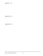
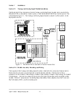
Figure 7.1.2
Tonnage & Analog Signature Module Mounting Dimenions
press control enclosure or it can be mounted in its own enclosure. If the unit is to be mounted in a
location subject to shock and vibration, shock mounts are required. Either the card rack assembly can be
shock mounted or the enclosure in which it is installed can be shock mounted.
In selecting the mounting location for the OmniLink II Press Automation Control Tonage and Analog
Setup module, the wiring connections for the unit should be considered. After the mounting location has
been determined, the card rack assembly can be secured with four screws. Mounting dimensions are
shown in Figure 7.1.2.
Summary of Contents for OmniLink II
Page 5: ...April 27 2004 Manual Version 1 01 iv ...
Page 7: ...April 27 2004 Manual Version 1 01 1 2 ...
Page 21: ...April 27 2004 Manual Version 1 01 3 8 ...
Page 44: ...April 27 2004 Manual Version 1 01 4 23 Section 4 5 4 N A ...
Page 45: ...April 27 2004 Manual Version 1 01 4 24 ...
Page 69: ...April 27 2004 Manual Version 1 01 7 14 ...
Page 77: ...April 27 2004 Manual Version 1 01 8 8 ...