April 27, 2004 Manual Version 1.01
7.2
TONNAGE & ANALOG
SIGNAL MONITOR
C
H
1
C
H
2
C
H
3
C
H
4
COM
02
01
03
04
I1
I2
I3
I4
+24V
COM
TX
R+
GND
R-
T+
T-
RX
GND
NEU
L1
SHLD
GND
CANH
CANL
TERM
PWR
R
+
-
C
S
R
+
-
C
S
R
+
-
C
S
R
+
-
C
S
Strain Guage Wiring*
* See section 7.4 for specific hookup instructions
R = VREF = Voltage Reference
+ = SIG+ = Signal Positive
- = SIG- = Signal Negative
C = GND = Common
S = SHLD = Shield
Power Connector*
L1 = AC Voltage 110Vac Input
NEU = AC Voltage 110Vac Neutral
GND = Ground Connection
High Speed Serial Bus
SHLD = Shield
GND = Blue
CANH = Orange
CANL = White
CAN Bus Termination Switch
Switch is located on circuit board in lower
left hand corner. Switch must be in “ON”
position (switch up) when device is last
unit in the can bus chain. Termination
LED will light when switch is turned “ON”.
Switch must be in “OFF” position (down)
when unit is NOT the last unit on the CAN
bus. Termination LED will be Off.
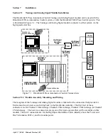
Figure 7.1.1
- Module Faceplate & Wiring
The faceplate and wiring are shown in Figure 7.1.1
The following connections and operations must be done:
1. Input Power
2. High Speed Serial Bus Cable
3. Set High Speed Serial Bus Termination Switch
4. Wiring for Strain Guages
To assemble the module, simply slide the base card into the single slot card rack. The module slides
into two guides of the rack, and is held in place with two knurled screws at the top and bottom of the
module.
The OmniLink II Press Automation Control Tonnage and Analog Signal module can be mounted in the
Summary of Contents for OmniLink II
Page 5: ...April 27 2004 Manual Version 1 01 iv ...
Page 7: ...April 27 2004 Manual Version 1 01 1 2 ...
Page 21: ...April 27 2004 Manual Version 1 01 3 8 ...
Page 44: ...April 27 2004 Manual Version 1 01 4 23 Section 4 5 4 N A ...
Page 45: ...April 27 2004 Manual Version 1 01 4 24 ...
Page 69: ...April 27 2004 Manual Version 1 01 7 14 ...
Page 77: ...April 27 2004 Manual Version 1 01 8 8 ...

