-23-
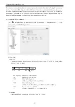
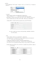
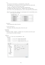
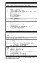
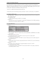
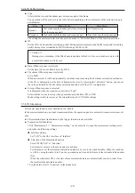
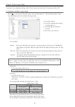
● Error Data and Special Character
St
Meaning
G
Normal Frame
B
SynchBreak error of LIN (When Dominant is 10bit)
S
SynchField error of LIN (At the time other than 0x55)
P
Parity error of LIN
L
Data length error of LIN ("ID"is set in "Frame End" setting )
R
When the data of the Response of LIN is less than 1byte
C
CRC error of CAN / Checksum error of LIN
A
ACK error of CAN
E
Error frame of CAN
F
Form Error of CAN(When CRC or ACK delimiter is 0)
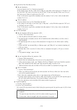
Display
Meaning
( )
Framing error (When the stop bit is Dominant.) e.g. (01)
LOSTDATA
Displayed in “Ch” field. It means there is lost of data while transmitting into PC.
CAPTURESTOP
Displayed in “Ch” field. It means capturing function is not running.
OVERRUN
Displayed in “Ch” field. It means the buffer in the analyzer becomes full while
measuring.
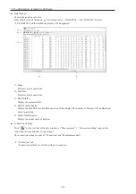
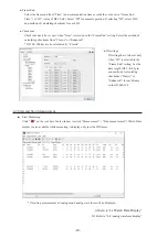
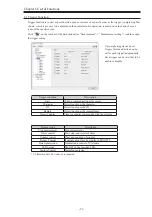
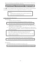
● Data Position
It displays the number of data loss (Analyzer cannot save data in the SD card or HDD of PC because of
the baud rate and large amount of data) while measuring. “LOSTDATA” will be displayed in the monitor
display.
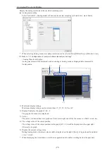
After the measurement, it will display the position of top of data displayed in the monitor display.
If the Capture Control Trigger stops capturing, “Capture stopping ...” will be displayed.
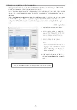
* When selecting Analog mode, only data of “Time”, “I1234”, “AI1 - 4” will be displayed if there is not
CAN/LIN data. It will be blank when there is no GPS/Acceleration data.
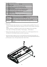
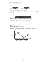
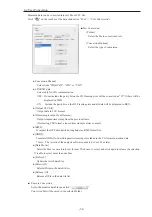
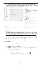
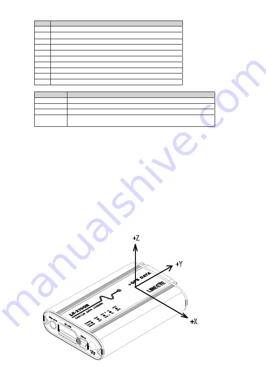
* The direction of the acceleration censor is as in the picture below. The upper side gives plus value. For
example, when the side of the Dsub25 port is the upper side (in other words, when RUN/STOP button side
is the bottom side), Y value will be plus and the X and Z values will be 0.
+Z
+Y
+X

