-15-
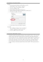
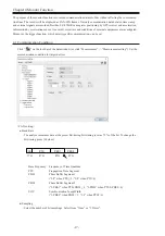
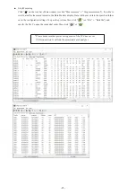
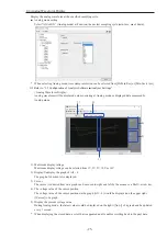
■ Analyzer Settings
Click “
” on the tool bar of the data window (or click “Measurement” -> “Measurement setting”) to set the
target bus, speed and so on. On the measurement setting window, every time you change the setting on the left
side of the window, the contents of the setting (on the right side of the window) will be changed. Click “
”
to save the configuration as a “.SU” file. Click “
” to read the configuration file.
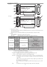
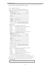
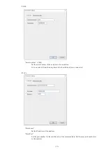
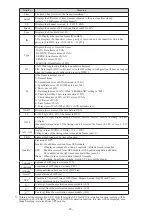
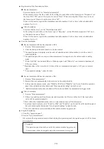
● Interface
Ch-1 interface/Ch-2 interface
Select the interfaces of CH1 and CH2 from CAN
or LIN.
Ch-1 CAN terminator
You can connect the terminal end (120Ω) to the
CAN port side of the Ch-1 in the analyzer.
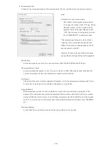
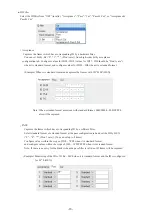
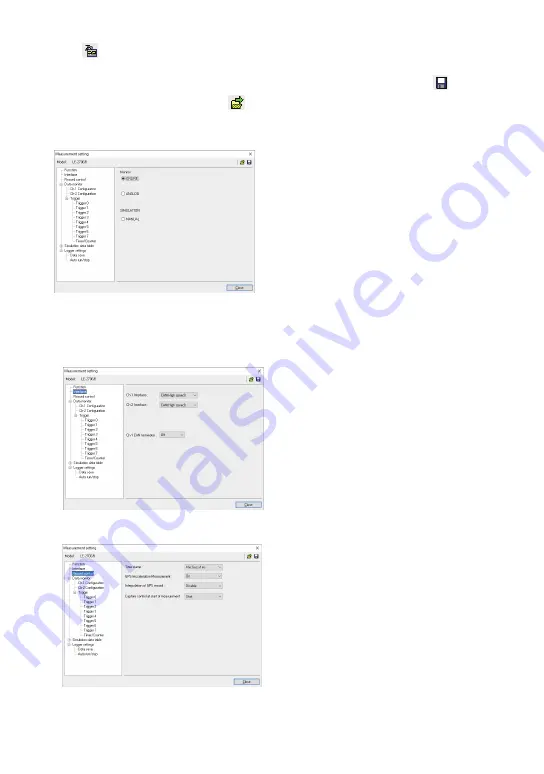
● Record Control
Set the resolution of timestamp, ON/OFF of GPS/
Acceleration
(*1)
function, interpolation function for
GPS data
(*1)(*2)
, and capture control at staring the
measurement
(*2)
.
*1: GPS function is available only in LE-270GR. It
is able to set GPS/Acceleration function in LE-
270AR, however, it cannot be performed.
*2: Firmware version 1.02 or above is required.
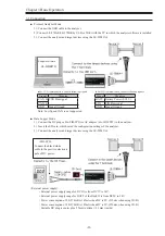
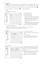
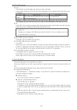
[ONLINE] (Online mode)
Monitor CAN/LIN data.
[ANALOG] (Analog mode)
Record 4 external signal (voltage) at specified
sampling (1ms - 10min). Analog mode records
not only the voltage data but also the latest
communication data captured between each
sampling cycles.
And, the relationship between external signals
and communication data is easily found out.
Refer to “4-4 Analog waveform display”
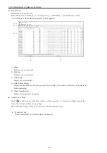
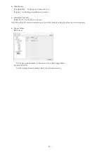
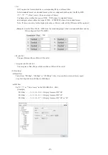
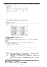
● Function
Select the mode of the analyzer.
“MANUAL” (Simulation mode)
It outputs the data which already set to the simulation data table from CH1(CAN1/LIN1).
“Schedule” Schedule setting for the analyzer when it is LIN master


