-11-
Chapter 3 Basic Operation
3.1 Connection
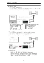
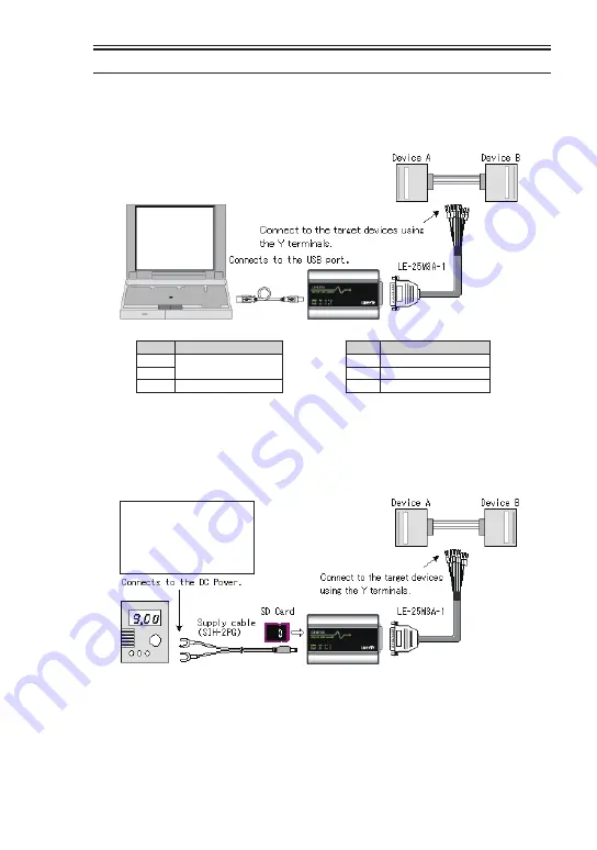
■ Protocol Analyzer Mode
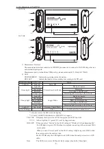
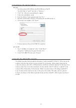
1). Connect the USB cable to the analyzer
2). Connect LE-270AR/LE-270GR by USB or Wi-Fi with the PC to which the analysis software is installed.
3). Connect the analyzer and target devices using the LE-25M3A-1.
■ Data Logger Mode
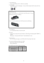
1). Connect the DC plug cable (SIH-2PG) or AC adapter (6A-181WP09) to the analyzer.
2). Insert the SD card, which saved the configuration settings of the analyzer.
3). Connect the analyzer and target devices using the LE-25M3A-1.
● For CAN communication, connect following signals.
Signal
Meaning
CAN_H CAN Bus signal
CAN_L
GND
Signal Ground
Note: Low Speed CAN is not supported.
● For LIN communication, connect following signals.
Signal
Meaning
BATT Battery Power (9-18V)
LIN
LIN Bus signal
GND Signal Ground
<SHI-2PG>
Connect the black/white
cable to the positive electronic
pole of DC power.
<External power supply>
・
External power supply range for DC IN is from DC7V to 34V.
・
External power supply range for BATT of the Dsub25 is from DC9V to 34V.
・
Power consumption of LE-270AR is 145mA when DC is 9V. (215mA when using Wi-Fi)
・
Power consumption of LE-270GR is 185mA when DC is 9V. (250mA when using Wi-Fi)
・
Suitable DC plug is center plus 5.5mm (outside) / 2.1mm (inside).
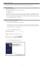
Analysis software
LE-LINK27R


