BLDC50/100
User Manual
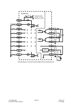
3.4 IO Control and Function Description
1
+5V USER
2
GND
3
X1
4
Y1+
5
X2
6
Y1-
7
X3
8
Y2+
9
X4
10
Y2-
11
X5
12
AH
13
X6
14
Analog In
15
X7
16
AL
17
X8
18
INCOM
PIN
NUM
SIGNAL
TYPE
SIGNAL NAME
FUNCTION
BASIC
GENERAL
BASIC
1
POWER
SUPPLY
+5V USER
The drive provides users with up to 100mA
+5V supply
2
GND
External control signal GND
18
INCOM
External opto-coupler power input (common
anode or common cathode connection can
dial to select)
3
INPUT
CW/CCW
X1
Clockwise/Counter Clockwise Select
5
STMD
(STOP MODE)
X2
Stop mode choice input
7
EN/RE
(Enable/Reset)
X3
Motor enable/disable. It can be used for
alarm reset as well.
9
SPST
(SPEED-SET)
X4
Internal/external speed-set choice
11
STOP
X5
The electromagnetic brake operation is
selected when the motor is stopped.
13
M0
X6
For multi-speed operation, the M0, M1, M2
signals are used in combination.
15
M1
X7
17
M2
X8
12
ANALOG
INPUT
Analog VCC
-
Using external speed potentiometer setting
speed
14
Analog In
-
16
Analog GND
-
Lin Engineering
BLDC 50/100 Driver Manual
Page 11
Version 1.0
01/29/2020


